Utilizing DIC Technique for Visualizing the Failure Modes of Concrete Specimens- Juniper Publishers
Civil Engineering Research Journal- Juniper Publishers
 |
Introduction
Surface displacement measurement of materials is an important part of various laboratory experiments. The DIC technique is an innovative particle tracking method by which the in-plane surface deformations are measured by comparing the digital images of a specimen surface taken during the experiment [1]. The increasing diffusion of DIC can be explained by its flexibility, scalability to a wide range of dimensions, the robustness of its operating principle, and its (apparent) ease of use” [2]. DIC was defined as “a non-contact whole-field imaging technique that employs tracking and image registration for accurate two-dimensional (2D) and three-dimensional (3D) deformation and strain measurements. It is a technique based on surface analysis methods which involve monitoring and identifying changes in a pattern applied to the surface of objects under observation, that have been subjected to some form of mechanical pressure or strain as shown in (Figure 1). DIC method was developed in the early 1980’s for measuring surface displacements and deformation with the first system developed at the University of South Carolina” [3 & 4] .This method “requires a digital imaging system to optically record images of the surfaces before and after deformation. The pair of gray level functions of the images were then compared using advanced image correlation and processing algorithms to determine the displacement and deformation gradients. Unlike laser speckle techniques, which required an optically rough, reflective surface and minimal vibration, the only requirement for surface condition was a visually speckled surface” [5]. A faster approach for image correlation was later developed by Sutton, et al. [6]. Instead of using the iterative approach, such as a coarse-fine method, a second order Newton-Raphson method was employed. A special technique “was then added to achieve a higher probability of convergence. This correlation method was later evolved into measuring in-plane and out-of-plane displacements using two video cameras separated by a predetermined distance. The lines of sight from two cameras may either be parallel to each other” [7] or form a pan angle between them [8]. “As soon as two image points are matched by correlation methods, the three-dimensional coordinates of the physical point may be determined. A surface contour may be generated from one pair of stereo images, while a deformation measurement requires the correlation of four images: a stereo pair before deformation and another after deformation. DIC of speckle patterns for engineering applications has been used extensively in many applications to measure displacement components and deformation gradients of an object’s surface due to deformation for over four decades” [9].

Principle of Digital Image Correlation - DIC
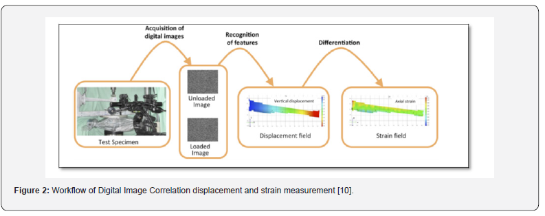
DIC is based on “sets of images of the surface of the specimen in the undeformed (reference) and deformed states (Figure 2). DIC can be implemented both in a bi-dimensional (2D-DIC, with a single camera) and a tri-dimensional (3D-DIC, using two or more cameras) version. A calibration is necessary to initialize the spatial correlation processes of DIC. The images are divided in smaller sub-images (facets), and a matching algorithm is used to match the facets between the reference and deformed states. The displacement field is then computed. Subsequently, the strain field is obtained by derivation” [10].
DIC Application Examples
Many examples where DIC technique has been applied for several aerospace applications are presented below:
Strain measurement in friction stir weld (FSW) samples
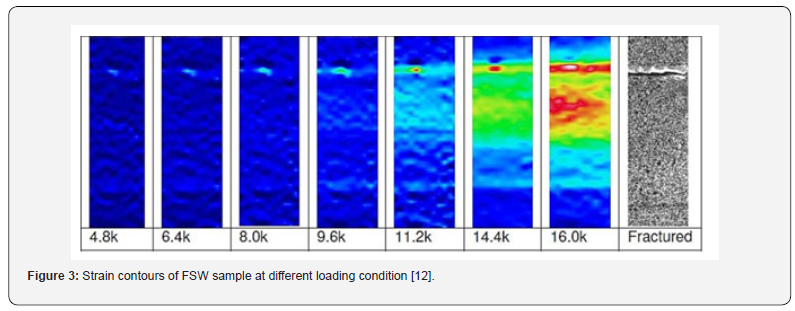
Friction Stir welding “is solid state welding process for joining metals by plasticizing and consolidating materials around the bond line using thermal energy produced from localized friction forces .This welding method is applied in many aerospace applications and is often required to inspect the welded region for the integrity of the welds. The material properties of the weld samples such as the Young’s modulus, yield stresses were also determined from the stress-strain graphs obtained by using the SPDIC tool. In addition, the pseudo colored strain contour maps as shown in (Figure 3) indicated the area of maximum strain and thereby predicting crack initiation in the sample” [11-12].
Measurement of High Strain Regions in Particulate Composite Sample
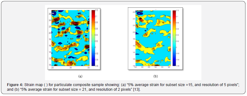
Particulate composites used for rocket fuels were analyzed by using DIC techniques. The main objective of this work “was to determine the high strain regions under low loading conditions that would possibly indicate regions of eventual failure under high loading conditions. This is important since the underlying causes of failure such as microcracks or other surface/bulk defects are not always detected by traditional NDE techniques. (Figure 4) shows the strain fields generated by using DIC for the particulate composite test sample. From the results obtained, it was demonstrated that there is a statistical distribution of high strain regions within the particulate composites. Based on the result obtained, it was demonstrated that DIC method may be used to identify very early on regions of eventual failure, and may also be used to change the distribution of particles in the particulate composite so as to obtain improved material properties” [13].
Full-field strain evaluation in helicopter drone composite rotor blade
Rotor blades “are usually subjected to high stresses due to their weight and the force created by irregular winds. DIC technique has been successfully employed to analyze these rotor blades under normal to shear stress conditions as well as in the bending fatigue test. GOM recently demonstrated the application of DIC technique to monitor the strain fields on composite rotor blade for helicopter drones in the laboratory environment subjected to bending test” [12].
Measurement of strains in shear panels of an aircraft
DIC technique “has also been successfully implemented to inspect the shear panel subjected to shear load for mapping whole-field out-of-plane displacement (buckling). GOM recently demonstrated that the out-of-plane displacement map generated from ARAMIS DIC software was in good agreement with the FEA results” [12].
Failure Modes of Concrete Specimens
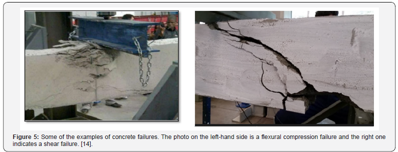
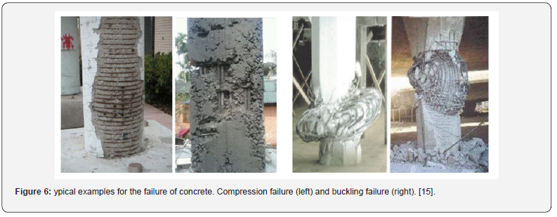
The concrete specimens, depending on its shape, can fail under various types of failures. The failure mode depends highly on the shape of the specimen as well as the action of forces i.e. compression, tension etc. In cubically shaped concrete specimen’s failure can be explosive or non-explosive, and its failure shape can vary due to compression and shearing. In cylindrical specimens, i.e. cores, failure mode are generally non-explosive and its shape is depended on the type of forces acting on the specimen such as splitting, shear or splitting and shear. Also, during the testing of the concrete specimen’s failure mode can be affected by lateral restraint. It is the inequality of lateral expansion between the steel plate of the compression apparatus and the actual specimens surface that is subjected to compression. The effect of lateral restraint eventually increases the shear stress which affects the failure mode of the specimen. This shear stress causes the specimen to fail through the center of it and with any explosive effect. In addition, the failure generally starts from the surface where the specimen is in contact with the platen of the apparatus. Generally, engineering materials for construction including concrete, steel, rock etc. have some similar characteristics under certain amount of loading. Typical examples of failures are flexural compression failure, shear failure, compression failure and buckling failure. Flexural failures occur when the shear strength of the specimen is higher than the flexural strength. Shear failures happen when the internal strength of the material which is controlled by various parameters exceeded by the applied load (Figure 5). Compression failures occur when the specimen is axially loaded until the yield stress of the concrete is expected to be exceeded. In this type of failure lateral expansion is generally not expected. When the specimen has a certain amount of height/width ratio buckling failure can be expected. Compared to compression failure, buckling can be easily achieved since the strength of the specimen will be much lower as well as the load carrying capacity. Eventually, buckling will be observed outwards. (Figure 6).
Literature Review
Choi & Shah [16] have utilized digital image correlation technique to measure the deformations on concrete specimens. The material itself assumed to be heterogenous thus making this technique intriguing for such conditions. The authors have aimed to use the technique to visualize the micro-cracks propagation. They have found out that the deformations along the specimens are not uniform even in the elastic range by using contour maps.Authors have noted that the technique can be very well used for measuring the deformations as well as the crack propagation throughout the laboratory testing. Shah & Choi [17] have chosen digital image correlation technique to observe and visualize the complex failure pattern in concrete blocks under compression. They have also pointed out that DIC is very useful in determining the microscopic fractures and strain localizations under loading and tension.
McGinnis et al. [18] have considered digital image correlation technique for determining the in-situ stresses in concrete structures. They have performed three-dimensional technique and used core-drilling method for determining the displacements. The core-drilling method can be used to determine stresses using displacements. They have found out that the normal stresses were calculated by an accuracy of 7 % with 3D digital image correlation technique which was accepted as an accurate approximation. Küntz et al. [19] have investigated the in-situ behavior of a shear along a bridge on a reinforced concrete beam. They have analyzed the behavior under static loading conditions by using a truck passing and stopping from different locations. The authors have concluded that this method can be used also for studying fatigue behavior of concrete structures under this kind of conditions. Corr et al. [20] have analyzed the surface contact area between carbon fiber reinforced polymer and concrete blocks by using digital image correlation technique. They have investigated the displacement and fracturing around that region in terms of the principles of fracture mechanics. According to their study, they have indicated that DIC technique can be used for accurate measurement of the displacements along the deforming materials. Also, they have noted that based on this kind of experiments it was even possible to build a constitutive law by using fracture mechanics for experiments.
Helm [21] has utilized digital image correlation technique for a challenging problem in concrete specimens. The author wanted to measure the surface displacements of the specimens with multiple crack propagation which he mentioned that it was a very challenging task. Author have noted that DIC technique is very effective for measuring multiple growing crack patterns. Shah & Kishen [22] have investigated the contact behavior between the different concrete specimens by using digital image correlation technique. The specimens have different compressive strengths and characteristics. Authors have pointed out that they were able to calculate the surface and sliding displacements as well as the properties of the cracks including the location, size and width.
Forquin [23] have utilized digital image correlation technique to determine the crack propagation speed in concrete specimens under tension. The author has used rocking spalling test on dry and wet samples for this purpose. He concluded that DIC technique is much more accurate than conventional methods such as crack gauges for this kind of experiments. Boulekbache et al. [24] have aimed to determine the fracture mechanism of concrete specimens under splitting tensile test with digital image correlation technique. The authors have utilized steel fiber reinforced specimens for this purpose. They have also investigated the effect of fiber addition and compressive strength on the behavior of the specimen during the test. They have found out that there are two different fracture mechanism where there were a main crack and secondary cracks after the main have been initiated.
Hamrat et al. [25] have done experiment on fiber reinforced concrete beams to determine the flexural cracking behavior of the specimens with different strength characteristics. They have investigated the physical properties of cracks including size and initiation as well as the displacements. They have noted that DIC technique can be very precise for displacement measurements. Also, according to their findings one of the most important aspect of digital image correlation technique is that it can be used to determine the cracks before happening. Some of the notable researches have been mentioned in this study related with the application of digital image correlation techniques in concrete specimens. It has been spotted that this technique has been used for generally the same application over the years. However, some intriguing usages can also be seen. A short summary of the literature review according to this study is given in Table 1.

Conclusion
According to this study, there are some important things to note related with the DIC and failure modes of concrete specimens.
General conclusion of this study can be summarized as follow:
a. DIC is a very low-cost technique compared with its capabilities.
b. DIC is being used in many disciplines of science and engineering.
c. DIC can be used to visualize the physical properties of the specimens, i.e. cracks, that are not visible to the naked eye.
d. DIC can be used to determine the expected failures even before happening.
e. DIC can be used to determine the failure modes of concrete specimens through displacement and strain diagrams.
f. DIC is found to be more accurate than conventional techniques by various researchers.
DIC can handle multiple crack growths and propagation on concrete specimens.
For more about Juniper Publishers please click on: https://juniperpublishers.com/journals.php
For more Civil Engineering articles, please click on: Civil Engineering Research Journal
https://juniperpublishers.com/cerj/CERJ.MS.ID.555783.php

Comments
Post a Comment