The Selection of Suitable Boundary Conditions for Finite Element Simulations of Deep Tunnels- Juniper Publishers
Civil Engineering Research Journal- Juniper Publishers

Abstract
In finite element simulations of deep tunnels an appropriate selection of the boundary conditions at the border of the model is important. Commonly, a system with vertically and horizontally fixed boundaries is used for finite element calculations of deep tunnels. In the contribution the shortcomings of this assumption will be explained and the requirements to the model size, which should be considered for this type of boundary conditions, are discussed. An alternative approach is also presented, which is derived from a commonly used approach for c and has been adapted to deep tunnels.
Mini Review
We speak of deep tunnels if the overburden height is much larger than the other dimensions of the model and therefore it is not possible or useful to model the whole soil or rock mass located above the tunnel. Moreover, the variation of the overburden stress level in the zone of the tunnel is insignificant compared to the amount of the overburden stress and therefore the stress level can be assumed to be constant [1]. All boundaries are assumed to be fixed vertically and horizontally (Figure 1). For finite element model of tunnels often the model size is chosen considering a distance of 3*D (with D being the tunnel diameter) measured for the tunnel to all boundaries in all directions, because it is assumed that in this case there is no more influence of the boundary to the tunnel reveal. The assumption of “all fixed” boundary conditions implies in this case that there is not only no influence of the boundary to the tunnel, but also that the displacements are zero in a distance of 3*D to the tunnel reveal, which is unrealistic in many cases. In fact, in this case due to the relatively small distance between fixed boundary and tunnel, the displacements of the tunnel are smaller than, which can lead to results on the unsafe side.

The solution to this problem can be found in increasing the model dimensions to have a distance to e.g. 6*D or more, depending on the properties of the soil or rock mass. Increased model dimensions lead, however, to a higher number of finite elements and increasing the model size e.g. by 2, the number of elements is increased by 4 (2-dimensional model) or even by 8 (3-dimensional model), with consequently higher calculation times.
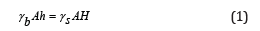
However, there is a possibility to avoid the afore-mentioned necessity to increase the model dimensions. As in use for shallow tunnels and many other geotechnical applications, a model with lateral boundaries fixed only in horizontal direction is proposed. The lower boundary is fixed vertically and on the free upper boundary is placed an elastic beam. This beam is necessary, because the stiffness of the soil or rock mass body must be considered; using only a line or sectional load would imply that the displacements in the zone over the tunnel would be transferred more or less directly to the ground surface, which is not realistic for deep tunnels. This elastic beam has therefore the purpose to apply the load of the overburden to the model and to simulate at the same time also the stiffness of the soil or rock mass body over the tunnel. The specific weight of the beam γb with the height h can be determined from the specific weight of the soil or rock mass γs considering the overburden height H and the ground surface of the model A using the following equation:
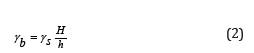
The specific weight of the beam γb can be obtained from Eq.
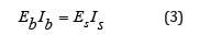
If we consider that the bending stiffness of the upper soil or rock mass body Es Is (with the Young’s modulus Es and the inertial moment Is ) is equal to the bending stiffness of the beam EbIb (with the Young’s modulus Eb and the inertial moment Ib ), we can derive Eq. (3):
with
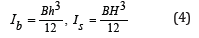
B is the width of the model. The Young’s modulus of the beam can be obtained from Eq. (5), which is obtained from Eq. (3) and Eq. (4):
The proposed model was used for finite element simulations for the Brenner Base Tunnel (Figure 2). The Brenner Base Tunnel (BBT) will be the world’s longest tunnel with a total length of 64 km and will connect as a railway tunnel Innsbruck (Austria) with Fortezza-Franzensfeste (Italy). The Brenner Base Tunnel is composed of two parallel main tunnels with a diameter of 9 m and 70 m and a smaller emergency tunnel in between the two main tunnels, situated 12m below. The system also includes three underground emergency stations, two connection tunnels to the existing Innsbruck railway bypass tunnel and also rescue and access tunnels. The proposed model could be used successfully to simulate many of the interactions between the numerous tunnel drives [2-5].

Conclusion
With the proposed model with boundary conditions used for shallow tunnels and fitted with an elastic beam with high specific weight, the shortcomings of the traditionally used system with vertically and horizontally fixed boundaries can be avoided for finite element calculations of deep tunnels [6]. This model has also the advantage that variable stresses over the height of the model can be obtained, whereas with the traditionally used system a constant stress level (the so called far-field stress) depending on the overburden height must be imposed for the whole model. The proposed model was used successfully for finite element simulations for the Brenner Base Tunnel.
For more about Juniper Publishers please click on: https://juniperpublishers.com/journals.php
For more Civil Engineering articles, please click on: Civil Engineering Research Journal
https://juniperpublishers.com/cerj/CERJ.MS.ID.555793.php


Comments
Post a Comment