Hydropower Applications for Very Low Heads - Experimental Work in Laboratory Conditions- Juniper Publishers
Civil Engineering Research Journal-Juniper Publishers
Abstract
In the economically developed countries, especially the ones of the European Union, increasing attention is paid to the possibilities of use of the hydropower potential at very low heads (i.e. from 0.5m up to about 2.5m). This substantial existing potential has not been used so far because it is generally not cost-effective to apply conventional water turbines. In the frames of several research projects, other machines have been developed and studied as hydropower converters for the range of very low heads. In this work, laboratory studies on the so-called Hydrostatic Pressure Machine (HPM) developed at the University of Southampton within the international research project HYLOW are presented. The parameter studies performed on a smallscale laboratory model in the frame of a subsequent research project served the improvement and the further investigations of the full scale prototype of the machine built on river Iskar in Bulgaria.
Keywords: Low heads; Hydropower systems; Hydroelectric converter
Research Area: Hydraulic Engineering; Hydropower
Introduction
The interest ofthe hydropower industry for the use of very low heads(i.e.less than 2.5m) is growingin recent timeintensively. On the one hand, thisis theresult ofthe ever-growing energy needsof our society.On the other hand, renewable energy sources (incl. water power) become increasingly more important. Inthe field of hydropower, this range of the very low heads remains in fact still unused.Thereasonsarenumerousanddiverse. It should be mentioned however that theexistinghydropowerpotentialin this head rangein Europeamounts to several hundredMW, andthe interest for the use of this potentialbecomes increasingly up-to-date. Furthermore, the application of conventionalwater turbines for such very low heads is in principlenot feasible.The devices for hydropower applications with very low heads have specific features. It would be not possible here to go into detail description of the existing devices, their structures, operational conditions and performance parameters. There are already large number of such recent review works. As an example, [1-3] can be mentioned.
In this connection,it wasa maingoal of thefour-year researchprojectHYLOWin the 7thFramework Programme of theEuropean Commission(completed at the end of February 2012)to develop,study and test a newpowerconverter forverylow head,i.e. for the head range 0.5-2.5m. As partof this project,the so-calledHydrostatic PressureMachine(HPM) was developed (Figure 1a),theoretically justifiedandtestedunder laboratory conditions. On the nextstage of development, the HPM prototypes weretested on a full scalein nature conditions as realoperating small hydropower plants, Figure 1b.Infulfilling this task, a research small hydropower plant with a full-scale prototype of the HPM was builton the riverIskar in Bulgaria[4,5]. This activitywas intendedfor tracing the construction and operation of completesmall power plantswiththeHPM comprising allnecessaryequipmentcomponents.This power plant was run underdifferent real operating conditionsand therefore alloweddecisiveconclusions about theactualpossibilities for industrial implementation of the HPM[6,7].
The mentioned research project had a successor one [8] within which substantial activities were aimed at improvement of the machine and its implementation conditions. In this connection, extensive laboratory experiments were carried out on small-scale models, and the main results were further tested in real conditions on the full-scale prototype of the machine. In this work, the concept of the experimental program and its most important results are shortly presented. At the end, conclusions are drawn about the implementation of the obtained results. These research activities are of particular importance since for the water wheels and the HPM, respectively, unlike the water turbines, there are no similitude laws available. Thus, the parameter studies in small scale and the subsequent confirmation of selected results on the full-scale prototype are decisive for the further development of such devices. WPM principle and theoretical efficiency curve.

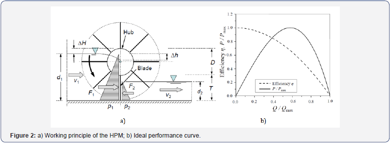
The qualitative difference between the HPM pressure machine from the water wheels is the pond effect of the hub. Thus, a concentrated head is created by the machine itself, and the blades are driven by the stream under pressure.
In fact, this is not a new idea. The so-called hydraulic pressure machine (originally in German: Staudruckmachine) uses this principle and was patented in Austria in 2006 by Adolf Brinnich. However, it can be discussed whether this device was not similar to the discharge measuring wheel of John Dethridge of 1910. Nevertheless, a consistent theoretical background of this concept was presented in [9,10] with the introduction of the HPM (Figure 2). With the mentioned basic reference works on the HPM, it is not necessary to go here into further details regarding the theory of the machine, its implementation conditions and performance. In the following, the recently carried out laboratory works in small scale for further improvement of the HPM performance will be shortly described.
Main parameters of the HPM model
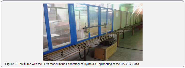
The described research activities were carried out in the open channel in the laboratory of the Department of Hydraulic, Irrigation and Drainage Engineering at the UACEG in Sofia, Bulgaria (Figure 3). A series of models of the HPM were built in a scale of 1:5. The scale was chosen to best fit the channel’s capabilities and to be compatible with previously performed research activities.
a. Diameter D’ :480mm
b. Width B : 400mm
c. Blade depth T : 140mm
d. Hub diameter D : 200mm
e. Max. blade velocity vB : 0.48m/s
f. Max. rotation speed : 27rpm
g. Average discharge Q : 26.7l/s
h. Max. power Pmax : 47W
Measurement system
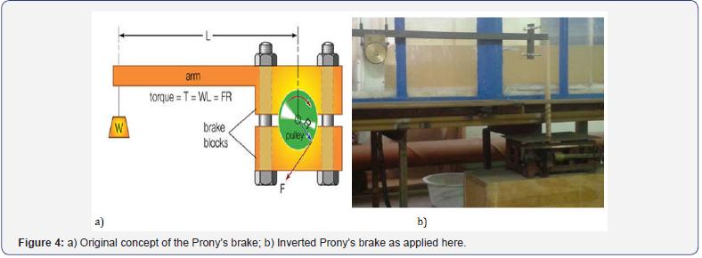
The measurement system was the possibly most simple one. The flow discharge was measured with a triangle measuring weir at the inflow of the test channel upstream of the model. The torque at the machine shaft was measured through the friction force by means of a Prony’s brakeand scales (Figure 4). Thus, the power limit of the HPM model could be reached, too. It should be mentioned that the original Prony’s brake works in tension (Figure 4a), while here; the moment arm was applied under compression (Figure 4b). This inverted implementation ensured a more stable operation of the device. The rotation speed of the model was measured with a stop watch, and the water levels upstream and downstream of the model were measured with piezometer cylinders. The laboratory program.
Models description
The program for laboratory research included 5 different models. In the following, they are introduced with their working designations:
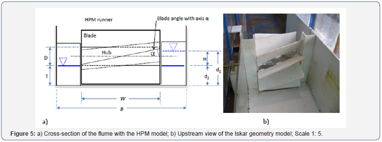
Iskar geometry (Figure 5): The model was made of PVC and had 10 inclined blades with depth of 140 mm and the inclination of α = 15°. The runner width and the other model parameters were as described above. The geometry corresponded to the original prototypebuilt on river Iskar in the frame of the HYLOW project [3,4,6,7]. With this model, experiments also were carried out with improved ventilation downstream, as described further below.
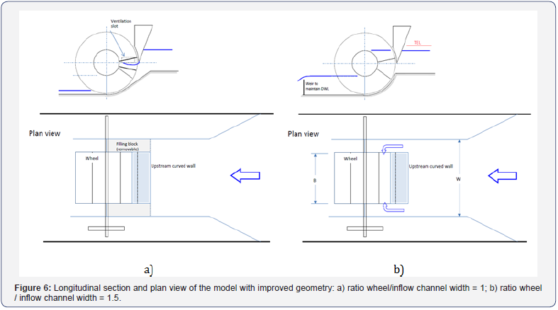
Improved geometry (Figure 6): This model was made of PVC, too. This model was tested with a curved upstream guiding wing wall, the ratio of the widths wheel/channel had the values 1.5 and 1, respectively. In the latter case (Figure 6a), the built side blocks allowed the water to enter the machine model only frontal. An improved ventilation downstream was tested here, too.
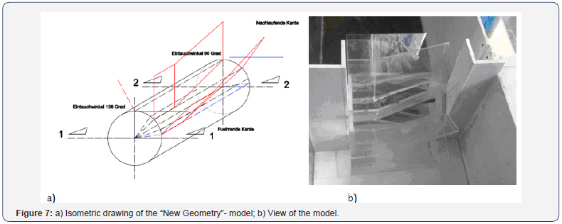
New geometry (Figure 7): The model was made plexiglass and had ten asymmetric blades with 140 mm depth. The runner width was 360 mm because in this way, additional air inflow was provided on the left side. The other parameters of the model were the same as mentioned above. This model was tested only with improved ventilation based on the results obtained already with the previous two models. The aim of the new asymmetric geometry was to reduce the insertion angle of the trailing edge of the blade. Therefore, the geometry was chosen asymmetrical, and the blade was quarter-point bent (Figure 7). This limited the blade depth at the leading edge. The blade was disposed below the axis line (Figure 7a), in order to create insertion angle of the trailing edge of 90°. The model was built entirely of plexiglass for improving the quality (i.e. the model stiffness) and reducing the leakages.
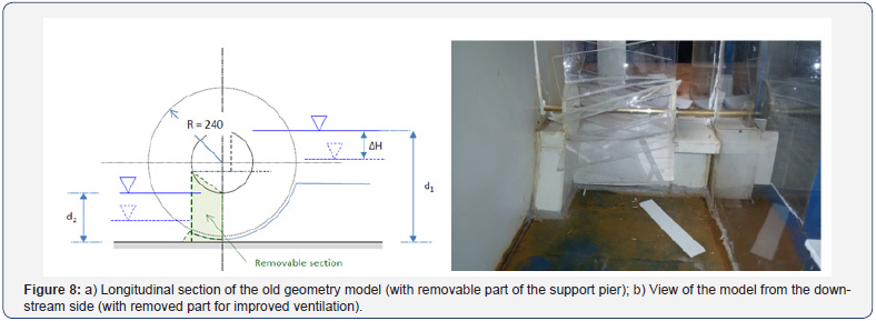
Old geometry(Figure 8): This was the scaled geometric model of the planned full-scale installation on river Iskar, but with increased upstream bed level and improved downstream ventilation of the blades. The model was with the diagonal blades and built entirely of plexiglass for improving the quality (i.e. increasing the stiffness of the surfaces) and reducing the leakages. The model had 10 inclined blades at an angle of 15° with respect to the longitudinal axis of the WPM.
Scaled Iskar geometry: The model had the original Iskar geometry with 10 inclined blades and was made of plexiglass but the runner width was 360 mm to provide additional air from the left side. The model also had increased upstream bed level and improved ventilation.
Test series and water level combinations
For all these above described 5 models, a total of over 70 different test series were carried out, i.e. series with different combinations of up- and downstream water levels. One test series includes 8 to 10 measurements of different rotation speeds. The characteristic water levels were as follows:
Upstream water level (UWL)- ΔH / D = 0 → UWL is at the top of the hub
ΔH / D = 0.1 → UWL is 2cm below the top of the hub
ΔH / D = 0.2 → UWL is 4cm below the top of the hub
ΔH / D = 0.3 → UWL is 6cm below the top of the hub
ΔH / D = 0.4 → UWL is 8 cm belo w the top of the hub
Downstream water level (DWL)- d2 / T = 1.0 → DWL is at the bottom of the hub
d2 / T = 0.75 → downstream water depth is 0.75T
d2 / T = 0.50 → downstream water depth is 0.50T
Parameters studied and main results
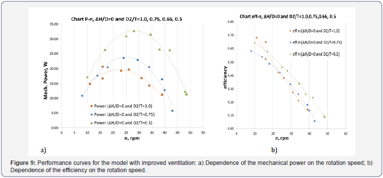
In the frame of the experimental program, the main traced parameters were mechanical power and efficiency in function of the rotation speed of the machine. In the following, the main results from the performed experimental studies are shortly presented. The next two graphs show the values of both investigated performance parameters for the model No.5, Old geometry (diagonal blades) with improved ventilation“. These graphs in Figure 9 represent the best obtained results, i.e. the maximum reached values of both performance parameters throughout the whole laboratory program. The curves with the same color correspond to the same combination of the water levels for mechanical power and efficiency, respectively (Figure 9). The maximum values of the observed and depicted here parameters were at the maximum head differences, i.e., the DWL was as low as possible, and the UWL was as high as possible but not higher than the upper edge of the hub, where additional hydraulic resistance in the machine operation would have appeared. This pattern was observed in all models.
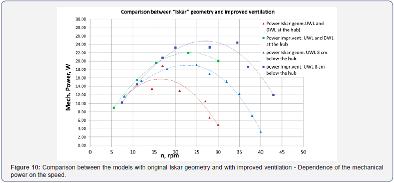
Furthermore, another comparison between the performance of the model with the original geometry Iskar and the same one but with improved ventilation was made as shown in Figure 10. From the graphical presentation it is obvious that the improved ventilation results in about 15% higher mechanical power (Figure 10).
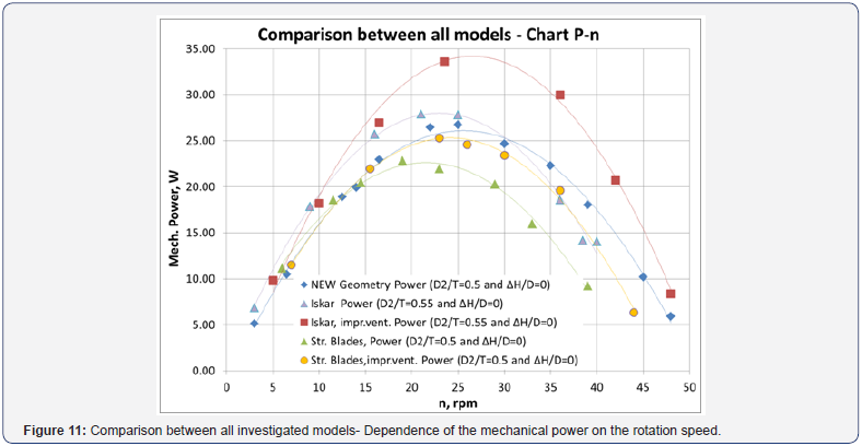
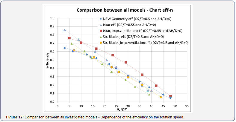
At the end, the performance of all models was compared with respect to the mechanical power as function of the rotation speed of the machine (Figure 11). It can be clearly observed that Iskar geometry with improved ventilation delivers the highest performance in the sense of this parameter, moreover, with a substantial difference to the other developments. The comparison between the obtained results for all models is similar with respect to the efficiency, too (Figure 12). This means that enabling downstream ventilation of the blades of the original geometry of the HPM leads to maximum improvement of its performance both as mechanical power and efficiency. All other investigated improvements of the approaching flow conditions and of the blade geometry did not prove to be comparatively efficient enough.
Conclusion
In general, the results confirmed the expectations based on previously performed similar research activities proving that the models were built with good quality, and the results are representative. On the basis of the carried out analysis of the obtained results, the following conclusions can be drawn:
a. The deflecting upstream wing wall did not supply any increase in the efficiency.
b. The raised inlet bottom did not deliver the expected increase in the efficiency of the machine performance.
c. The smaller leakage losses in the newer models did not prove to be decisive for increasing of the machine efficiency, either.
d. The effect of the Downstream Water Level (DWL) on the model performance proved to be of crucial importance. The lower the DWL, the greater the efficiency of the model operation.
e. A decrease of the efficiency values was observed for higher rotation speeds and .
f. The improved downstream ventilation of the model (i.e. of the upcoming blades) resulted in about 15% higher efficiency values.
g. The greatest influence on the performance results in the sense of mechanical power and efficiency has the machine operating head. As already noted above, the DWL should be as low as possible in this connection. As expected, the Upstream Water Level (UWL) leads to the best results with respect to the mentioned parameters when being at the top of the machine hub.
Acknowledgement
Carrying out the above described research activities was possible only within the international research project “Development of an ecologically compatible modular system for the use of low power and low heads water power systems” (in German: “Entwicklung eines ökologisch verträglichen, Modularen Systems zur Nutzung kleiner Wasserkräfte mit niedrigen Fallhöhen”) funded by the German Federal Ministry of Environment and reactor safety, subsequently by the German Federal Ministry of Economy and energy. Coordinator of the project was Prof. Dr.-Ing. Nicole Sänger from Hochschulke Darmstadt, Darmstadt, Germany.
The here described research activities were carried out in the Laboratory of the Dept. of Hydraulic, Irrigational and Drainage Engineering at the Univ. of Architecture, Civil Engineering and Geodesy (UACEG) in Sofia, Bulgaria, and would have not been possible without the kind assistance of Mr. Angel Karadzhinov, MSc, and Mr. Valentin Marinkov.
For more open access journals, please click on: Juniper Publishers
For more civil engineering articles, please click on: Civil Engineering Research Journal


Comments
Post a Comment