Assessing the Suitability of the Cold Bending Method in Fabricating Free-form Façade Panels- Juniper Publishers
Juniper Publishers- Journal of Civil Engineering
Abstract
Free-form buildings are one of the latest unique
trends in the construction industry worldwide. A number of projects have
been undertaken in different parts of the world. These structures are
hailed for their stunning aesthetics and jaw-dropping curvatures.
However, the design, fabrication and installation of free-form façades
is very difficult process as it requires unprecedented precision.
Free-form façade construction could yield such distresses as towering
costs, leakages and panel twisting if not well managed from early
stages. The choice of a production method is paramount as it impacts on
both the cost and the aesthetics of the structure. This study dwelled on
the use of cold bending for fabrication of free-form façade panels.
Design BIM data of a small free-form building in Korea and later mock-up
panels was overlapped and compared with the As-built data of the panels
obtained by laser scanning. The discrepancy in the panel data before
and after construction was assessed and attributed to the method of
panel fabrication used. It was then concluded that cold bending is
suitable for fabrication of flat and single curvature metallic panels,
but has limitations for double curvature panels depending on the degree
of curvature and expertise of the fabricator.
Keywords: Free-form construction; Laser scanning; Cold bending; Overlapping comparison; Panelization; Mock-up panel fabrication
Abbreviations: BIM: Building Information Modelling; DP: Digital Project; LIDAR: Light Detection and Ranging; RADAR: Radio Detection and Ranging
Introduction
Background and purpose software
Free-form design has increasingly gained popularity in the recent 'zero' decade [1].
This is mainly attributed to the increase in the use of computers to
easily produce complex designs in a comparatively short period of time. A
free-form building refers to 'all or portion of a building that is
sloped, narrowed, deformed, or consisting of irregular curves instead of
quadrangle' [2].
With the introduction and advancement of digital
design and Building Information Modelling (BIM), the plight of
realization of free-form buildings has become increasingly easier. The
computer applications have enabled world renowned designers like Zaha
Hadid and Frank Ghery, who have come up with the curvy, slender, wriggly
landmarks of the modern age.
The most difficult process in constructing free-form
buildings is to form and fabricate the façade. To incarnate the facade,
the complex geometric shapes of the façade should be divided into the
panels with the forms and sizes that can be manufactured and fabricated
efficiently. Optimization of façade panels is carried out during design
so as to derive the most cost effective and aesthetic panel curvatures.
There are several methods of forming and fabricating
freeform panels used all over the world. The most common ones include
hot bending, cold bending, hydroforming, die forming and others. The
choice of the method to be used depends on the cost, curvature of the
panels, and manufacturing speed. This study focuses on the cold bending
method of metal sheet processing and its application in the forming and
fabrication of free form panels. With cold bending, curved surfaces are
produced by forcefully bending and fixing flat, thick, sheet metal
pieces along the curved surface on site [3].
One of the drawbacks of cold bending on metallic
panels is the visible gaps at the joints of each panel which distorts
the beauty of the façade. However, not so much information has been
published which thoroughly scrutinizes the application of cold bending
of metal panels on free-form buildings. This study intends to assess the
suitability of the cold bending method on free-form buildings by
pragmatically analyzing the difference between the as-built and the
as-planned façade parameters.
Scope and method
The façade panel materials of free-form buildings
include glass, aluminum, steel, Glass Fiber Reinforced Concrete (GFRC)
and many more, among which aluminum is the most frequently used. This
study focuses on the design, fabrication and inspection of aluminum and
GFRC panels to create free-form facades. The followings are research
processes to meet the research objective:
a) Through literature review, the theoretical
drawbacks of the cold bending method were investigated. Two freeform
building projects whose panels were fabricated by cold bending were
identified for practically reviewing real-world problems.
b) Haewoojae, another free-form building fabricated
with the cold-bending method in Korea, was selected to measure the
difference of the as-built from the as-planned. As-built results of
Haewoojae were extracted through 3D laser scanning technology,
overlapped with the as-planned data of the facility, and compared to
gauge the magnitude of deviation with the as-planned data.
c) In order to make the findings of the comparison
more reliable and generally acceptable, mock-up aluminum and GFRC panels
of various curvatures were fabricated under the supervision of a group
of 4free-form fabrication and installation experts.
d) The as-designed and as-manufactured BIM data of
the mock-up panels were also compared with the overlapping method and
the causes of the deviations analyzed. The comparison results were used
to establish the circumstances under which cold bending is applicable as
a method of freeform panel fabrication.
Literature Review
Definitions
Free-form shapes play an important role in
contemporary architecture. To form the curved facade, the facades of the
freeform buildings should be divided into the shape and size that can
allow production and fabrication, which is called panelization [4].
Panelization methods change depending on the shape of free-form
surfaces, designer's intention, and panel creation algorithm. However
they can broadly be classified depending on the shape they take up, for
example, triangular, quadrangular, or polygonal.
Free-form panels can be majorly classified into three
categories according to curvature. Panels with curvature less than 5mm
are termed as flat panels, those with curvature bending in one direction
are termed as single curvature panels, while those with curvature
bending in two directions are classified as double curvature panels [5].
At the design stage of a free-form building,
designers create very complex 3D building shapes that reflect their
design inspiration. The initial panel models to embody these shapes
consist of free curves with curvatures that change in many ways, causing
difficulty in production and fabrication. Designers need to adjust the
initial panel models to secure constructability at reasonable cost while
maintaining the aesthetic quality of freeform shapes and surface
smoothness. This process is called panel optimization [6]. The bigger the curvature, the more difficult it is for the panel to be constructed and thus a higher cost.
Panel forming methods
There are various methods that can be used in forming
metal free-form panels. Cutting, roller bending, and pressing are
methods generally used to fabricate curved surfaces. Special forming
methods such as stretch forming, die casting, single point forming,
die-less forming, hydro-forming, multi-point forming, and explosive
forming have also been used [3].
Various processing methods are used together according to the required shapes of panels. Lee and Kim [3]
carried out the case study of mass customization of double curved metal
façade panels using a new hybrid sheet metal processing technique. The
authors, who were façade consultants on the Dongdaemun Design Park,
which was the first free-form building built in Korea, undertook the
study because the available panel manufacturing techniques at the time,
including cold bending, were not appropriate for the very curvy building
designed by Zaha Hadid.
Cold bending
Metal bending refers to an operation in which a
portion of a metal is flexed along a line or curve until a bend is
obtained. While metals can either be bent at room temperature or with
application of heat,cold bending is a metal bending method by forcefully
bending and fixing flat, thick, sheet metal pieces along the curved
surface on site at room temperature [7].
The biggest drawback of metal bending is spring-back,
or back returning force within the metal. A metal always tends to go
back to its original shape after the deforming force has been withdrawn.
Spring-back is 'the amount of elastic distortion a material has to go
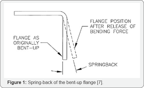
through before it becomes permanently deformed, or formed [7]. Figure 1 shows spring-back of a metal flange.
There are several factors that influence the amount of springback of a metal as follows:
a) Ductility of material: Spring-back in more ductile
materials is less than in rigid or less ductile materials. Therefore
metals such as aluminum although fairly ductile with a ductility of 0.65
[8] is bound to experience a certain amount of spring-back when bent.
b) Size of metal segment: Larger area segments tend
to have more spring-back than smaller area segments. Flatness of the
surface is also difficult to produce due to the 'oilcan effect'. This is
when a surface snaps back and forth like an oil can when pressed upon
by hand. It can be corrected through a costly procedure of submitting
the surface to pressures excessive of its modulus of elasticity using
hydraulic press.
c) Bending angle: The sharper the angle the lesser
the spring-back. Obtuse angles are more prone to spring-back than acute
angles. Therefore since the curvature of the freeform panels is not
acutely sharp, even for double curved panels, the panels formed using
cold bending method are bound to deviate from their original curvatures
due to spring-back.
d) Bend radius: The bend radius (curvature) has a
profound effect on the success of the bending operation. The radius
depends majorly on the material thickness and material hardness.
This study identified two free-form building projects
where cold bending was applied. While the projects demonstrated their
aesthetic features with curved facades, some drawbacks were identified
due to spring-back of a metal.
J Museum
Designed by a France studio XTU architects, Jmuseum
is a meandering free-form structure developed by the regional Korean
government as a part of the efforts to preserve the Asian History and
promote tourism. The double perforated walls of the 6,700m2
building, enveloped with rectangular stainless steel panels, references
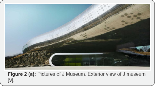
the pattern of a reptile skin that reflects the peripheral scenery [9].
Figure 2a
shows exterior view of the stainless steel envelope of the museum.
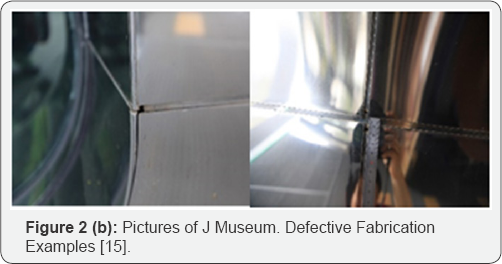
However, on some parts of the envelops, the panel joints were observed
to be staggering in an irregular pattern, insinuating a problem in the
fabrication or cold-bending method as shown in Figure 2b.
Experience Music Project (EMP)
This is a contemporary popular culture museum located in Seattle Washington, USA [10].
The 13,000m2 museum designed by Frank Gehry consists of a sheet metal
façade that was fabricated using cold bending methodology. The roof is
made up of 21 thousand panels of stainless steel with shades of purple,
silver and gold, aluminum and painted red and blue. However, as shown in
Figure 3, the tendency to spring-back and the gaps created around the panel joints due to cold bending are clearly visible.

Case Study
This research utilized Haewoojae as a specimen for
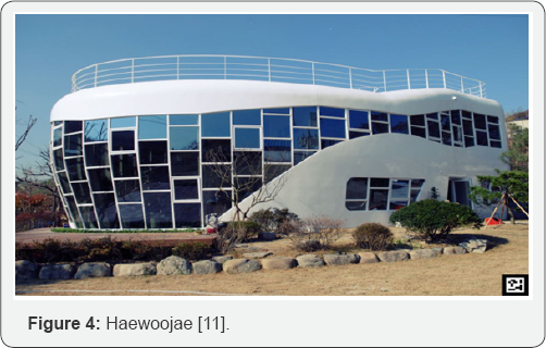
measuring the cold-bending problem. Haewoojae is a toilet museum built
in 2007 in Korea. Shown in Figure 4, the facility is two-story having 418m2 gross floor area, of which glass and aluminum panel façade consists of free-form panels of various curvatures [11].
As planned data
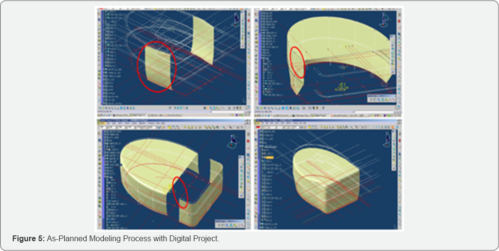
Figure 5
represents Haewoojae modeling results and process with Digital Project
(DP). DP is a commercial software produced by Gehry Technology in 1992
on the basis of CATIA program. Panelization was performed with
rectangular and triangular panel shapes. The basic panel size used in
the modeling was 1m x 1m and smaller ones were applied depending on the
building curvatures configuration.
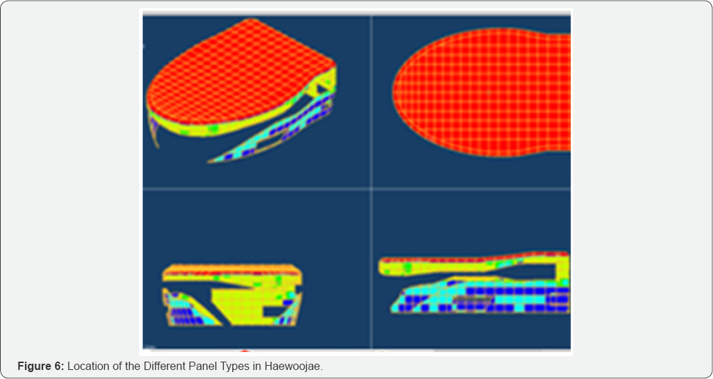
A total of 533 panels along with 4 different panel
types were identified through panelization: 262 flat panels, 204 single
curvature panels with curvature less than 200mm, 63 single curvature
panels with curvature more than 200 mm, and 24 double curvature panels. Figure 6
demonstrates the panel types with different colors: red - flat panels;
blue -single curvature less than 200mm; yellow -single curvature more
than 200mm, and green -double curvature panels.
Panels with large curvature were seen in the 1st and
2nd floor joints, the 2nd floor and roof joints, and the front and rear
curved areas of the building. While it was desirable to produce
the large curvatures panels with computer-based
digital production process for example using CNC machine to secure
after-fabrication aesthetic quality, all of the panels were formed and
fabricated with the cold bending method in the job site by the handymen
using 2D drawings of the facility.
As-built data comparison
3D laser scanning technology was used to obtain
as-built data of Haewoojae. 3D laser scanning is a relatively new
technology that uses light detection and ranging (LIDAR) to extract 3D
accurate representations of objects [12].
It is very similar to radio detection and ranging (RADAR) but the laser
technology utilizes light to measure range or distance instead of
radio.
Since the initial data generated by 3D laser scanning
technology has only the location information represented with point
clouds, the volume elements of a panel is not to be obtained
automatically so that parametric conversion of the data was impossible.
Just like getting the as-planned data of Haewoojae with DP, this study
utilized DP to produce the surface outlines of the scanned facility data
and converted those to BIM parametric data for comparison.
There are several previous research that adapted the 3D scanning technology in the construction industry including Su et al [12], Shin and Huang [13], and Park et al. [14].
The research mostly focused on the procedures and manipulation
techniques of capturing current data of buildings, geotechnical
configurations, and existing infrastructure deterioration conditions as
well as differentiating before and after conditions of certain objects
through a superimposing technique.
Data superimposition comparison
This study utilized the data superimposition method
to identify the differences of the after-construction results, i.e., the
as-built, from the as-planned design of the facility. Comparative
analysis was performed on the five regions of the facility as shown in Figure 7
(i.e., location 1, 2, 3, 4, and 5) with respect to whether the
curvatures of the panels in each region are accurately maintained. Figure 8
shows the three-dimensional comparison of the facility mass.
Red-colored areas indicate that the panels in the areas were overall
produced and fabricated as planned. On the contrary, the areas in white
color include the panels of which shapes and curvatures were more or
less different from as-planned.
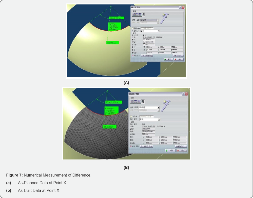
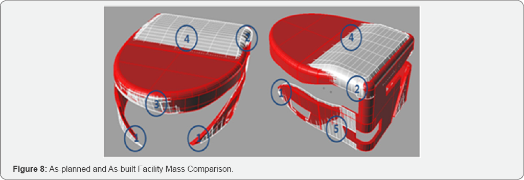
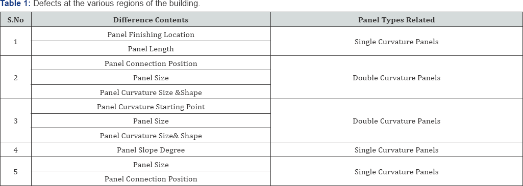
Table 1
summarizes the differences. Discrepant contents in region 1, 4, 5 take
place in the single curvature panels while regions 2 and 3 involve
double curvature panels and their unlike contents show different
features from regions 1, 4, and 5. Based on the superimposition
comparison, it can be inferred that as the curvature gets more complex
and bigger, the panel changes during forming and fabrication become
bigger.
Data quantitative comparison
In order to numerically measure the difference
between the as-built and the as-planned products, spreadsheet
application was performed along with one panel in region 2. Figure 7a & 7b
presents the measurement results delivering the X, Y, and Z-coordinates
of a specific point on the as-planned panel (X,Y,Z = 9188, 5788, 7000)
and the as-built panel (X,Y,Z = 9188, 5788, 7050).
The existence of a 50mm difference at Z coordinate
means that the designated panel at region 2 was constructed 50mm higher
than initially planned, and the panels that are next to the panel also
would be twisted from their original coordinates because of this error.
This twisting may cause lifting of panels and panel joints, water
leakages, and falling off finish materials when fixing the panels to the
main or sub frames [15].
Mock-Up Fabrication
The main objective of this research is to measure
as-built quality of the free-form panels formed and fabricated with the
cold bending method. While the best practice to meet this research
objective is to perform empirical tests using diverse panels through
case studies, there are very few free-form buildings available to test
for cold bending and furthermore, the contractors of the buildings do
not want to use their facilities as case study objects where 3D laser
scanning technology is used to reveal the quality of built outputs.
The authors instead produced mock-up panels by cold
bending. This will help to make the findings from Haewoojae more
reliable and generally viable. The mock-up panels were made with
aluminum and GFRC (Glass Fiber Reinforced Concrete) which were the most
commonly used in free-form buildings in Korea. A total of 8 panels
including one flat panel, two single curvature panels (one with
curvature more than 200mm and the other less), and one double curvature
panel with 800mm x600mm size each other were produced from each
material. During mock-up panel production, 2 experts of each material
were in attendance and advised on the physical properties of the
materials, fabrication, equipment usage, and surface machining methods.
Mock-up production process
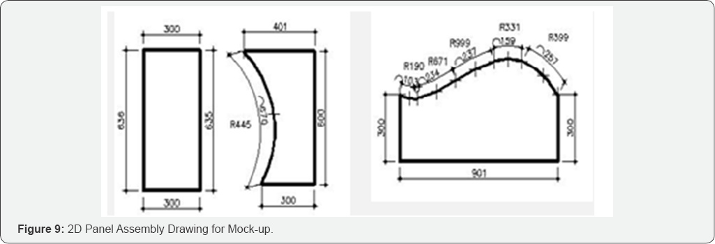
Constructing free-form façade panels with cold bending technique requires 2D fabrication drawings. Figure 9
shows the 2D drawings of the double curvature panel to be used for
producing mock-up panels for this study, which were extracted from the
3D BIM modeling data. The single curvature surface has one curvature
value so that the 2D drawings can be easily defined from the 3D BIM
data. But as for the double curvature surface, points and lines in the
drawings should be approximately drawn with a certain range of error and
close attention needs to be paid during the actual production of the
panels so as to keep the error within that range.
Aluminum mock-up panel production.
Carving, casting to pour, and solidify material are not appropriate for fabricating metal panels [3].
Cutting, roller bending, and pressing are methods generally used to
fabricate curved metal surfaces. In the case of roller bending, the
radius of a curved surface must be more than 200-300 mm. If the radius
is less than 200mm, then press bending is used.
The flat and single curvature mock-up aluminum panels
were produced by roller bending and press bending techniques. During
roller bending, the aluminum sheet was placed between a surface
controlling roller and a fixed roller set with the desired curvature. A
press bending machine pushes and folds a sheet metal panel. Both roller
bending and press bending are typically used to produce a uniformly bent
shape, but are not suitable for creating a bent shape with varying
curvatures or double curvature panels.
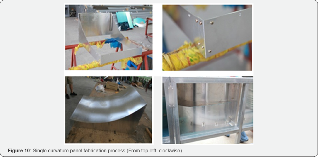
When producing the flat and single curvature panels,
the sub-frames were in the first place cut with a CNC machine and the
four sides of a panel were assembled using bolts before fixing a sheet
on top. Figure 10 shows the single curvature panel fabrication process.
Unlike the flat or single curvature panel, the double
curvature panel can be easily flattened by tensile force so that an
intermediate sub-frame was added in the mock-up production. Discussing
with the experts, it was found that the double curved panel with concave
curvature can be fastened to the mainframe by its edge with small
possibility of deformation, but in case of the convex curvature, the
sub-frame was definitely necessary to maintain its curved shape.
The authors tried to form and fabricate the mock-up aluminum double curvature panel with the procedure shown in Figure 10,
but since aluminum could not bear the bending stress, it got destroyed
during fabrication. The panel was so that formed with the combination of
press bending with hammering depending on the panel-forming workers'
proficiency.
GFRC mock-up panel production
In manufacturing GFRC panels, formwork fabrication is
the most important activity. Since it is not possible to use a
structured formwork for free-form façades such as Euro form, a separate
formwork should be produced and in the first place molds must be made
for producing the formwork. Molds can either be made from wood or
Styrofoam. Styrofoam was used in this study. The mold was produced by
entering its 3D geometric information into a CNC machine, which
automatically produced the mold as shown in Figure 11a.
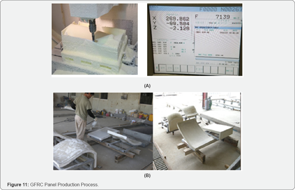
Having manufactured the mold, the formwork for making
GFRC panels was then produced by pouring concrete into the mold. GFRC
materials were then mixed and poured into the formwork, steam cured for
8-9 hours and then the formwork was taken off from the GFRC panel (See
left picture of Figure 11b). The panel was painted with 2 coats of the desired colors as the final step in the manufacturing of the GFRC panels (Figure 11b).
Mock-up data analysis
The superimposition method based on 3D laser scanning
technique was used again to compare the as-manufactured with
as-designed mock-up panels. Figure 12 shows as-designed mock- up data while Figure 13 as-manufactured ones respectively. The upper parts of the panel pictures and table data in Figure 12
are about 4 aluminum panels and the lower parts 4 GFRC panels. The
first panel shapes in both the upper and lower parts are flat panels,
the second and the forth single curvature panels, and the third double
curvature panel (i.e., (C) on the double curvature aluminum panel, (C-1)
on the double curvature GFRC panel). Figure 13 delivers the same formation of data layout as Figure 12 regarding as-manufactured panel data.
Reviewing the X, Y, and Z coordinates in Figure 12 & 13,
it is understandable that the aluminum mock-up panels demonstrate
bigger discrepancy than the GFRC panels. This tendency can be explained
in conjunction with the material features, so to speak, the spring-back
of aluminum and flexible workability of concrete.


Table 2 summarizes the discrepancy of the as-designed and between point 1 and point 3 was 3cm [2].
This discrepancy was as-manufactured coordinate points of the double
curvature found to exceed the aluminum production allowance provided
aluminum mock-up panel. The length difference between point by the
Korean Industrial Standard in Table 3.
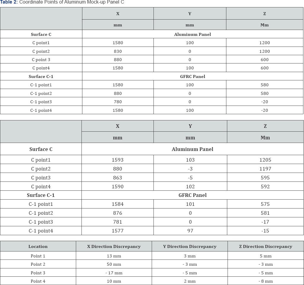

It would therefore pose problems like twisting at the
time of fixing a number of aluminum panels side by side on the
mainframes and sub-frames as designed. This twisting could also lead to
other defects in the long run, such as bulging, water leakages, and
failure of some finishing materials.
Summary & Limit
Through a case study and a mock-up panel fabrication
test, the study demonstrated that cold bending of metal sheets with a
roller or a press seems to have difficulty in meeting the as- planned
shapes of double curvature panels. Although there could be controversy
regarding the worker's level of expertise in handling the panels,
considering the fact that the workers in Haewoojae and the mock-up panel
test have been involved in the architectural façade fabrication field
for more than 10 years and successful in a number of projects, using a
cold bending technique for forming double curvature panels needs careful
technical consideration for securing quality free-form products.
In parallel with proceeding the mock-up test,
interview was conducted with the 4 experts who consulted for the mock-up
test to get an advice on their experience. Referring to the EMP as an
example, they pointed out that cold bending is not suitable for double
curvature panels. While the EMP demonstrated the use of cold bending in
its double curvature panels, only small pieces of sheet metal were used
for double curvatures and for mild curvature panels, large pieces of
sheet metal were utilized to minimize the breaks among the panels.
Despite this design consideration to prevent discontinuity of curvature
due to the breaks from occurring, the breaks made during cold bending
are easily observed.
It was the experts that commented in case where only
cold bending technique is available for free-form façade fabrication, it
is better to design a façade surface having shapes and curvatures that
can be divided into smoothly bent single curvature panels rather than
using complex curved surfaces. As well, it was discussed that providing a
certain range of tolerance in panel joints to the extent where the
visual continuity of curvature among panels is maintained is necessary
to obtain aesthetic free-form products.
While the findings from this study are beneficial to
designers, contractors, and project owners for securing quality
free-form products, there is certain limitation to bring out advanced
inferences for future application due to the limit of case study
materials. As more free-form projects are built in the future, the
authors will perform advanced research to deliver more reliable
findings.
Conclusion
Free-form buildings are known to be difficult to
construct due to their unique shapes and non-conformity to conventional
building techniques. The façade design and installation is considered to
be the most difficult stage in free-form construction. This is because
the facades require cutting edge accuracy in the design, panelization,
optimization, fabrication and installation of façade panels in order to
be delivered as intended by the designer. Therefore ultimate care should
be taken during each of those stages as any mistake could lead to dire
consequences for the project. The choice of material and method of
production of the panels has always been a point of concern for the
free-form design and construction teams. Choice of an unsuitable
material or fabrication method could lead to escalation of costs and
problems during and after installation of the façade panels.
This study focused on cold bending method of
free-form panel manufacturing and installation. Three free-form
buildings namely Haewoojae toilet museum and J museum in Korea, and
Experience Music Project in the United States, whose panels were
fabricated by cold bending were reviewed. The as-built BIM drawings of
Haewoojae were obtained by 3D laser scanning and compared with the
as-planned drawings by the superimposition technique. The results of the
comparison showed that the installed facade panel data deviated from
the originally planned design data.
In order to make the findings more reliable, mock-up
panels made of aluminum and GFRC were designed and fabricated by cold
bending. The panels of each material were of three curvatures types
namely flat, single curved and double curved panels. The flat and single
curved panels' data was found to match. However, the data for the
double curved panels for both aluminum and GFRC was found to have a
certain deviation which exceeded the Korean standard allowance limits.
This would pose problems like twisting at the time of fixing several
aluminum panels side by side on the mainframes and sub frames as
designed for the free-form structure. This twisting could also lead to
other defects in the long run, among others; bulging, leakages, falling
off of some components.
Cold bending was therefore found to be suitable for
manufacture of flat and single curved metal panels. For the case of
double curved panels, cold bending was found to be applicable to a
certain limit of curvature of the panel depending on the expertise of
the manufacturer.
For More Open Access Journals Please Click on: Juniper Publishers
Fore More Articles Please Visit: Civil Engineering Research Journal


Comments
Post a Comment