Finite Element Analysis and Theoretical Study of Punching Shear Strength of Concrete Bridge Decks- Juniper Publishers
Juniper Publishers- journal of Civil Engineering

Abstract
The problem of punching shear usually arises in
reinforced concrete slabs subjected to concentrated loads and
particularly in concrete
bridge decks due to the
development of an internal arching system. Ongoing research revealed
that the governing mode of failure for concrete bridge decks is not
flexure and that using the flexural design method usually led to
unnecessary high levels of steel reinforcement. This paper examines the
applicability of the non-linear finite element formulation of restrained
concrete bridge decks. A special purpose finite element program
FEMPUNCH was developed and employed in this study along with the
commercially available finite element programs. The accuracy of
non-linear finite element analysis is demonstrated using test results
conducted by other researchers. The results of the finite element
analysis are also compared to those obtained from a non-linear mechanics
model developed by Mufti and New hook. The experimental results and the
theoretical model provide insight to the fundamental behaviour of
concrete bridge decks.
Keywords:Polypropylene; FEMPUNCH; Bridge deck slabs
Abbrevations:GFRP:
Glass Fibre Reinforced Polymer; PFRC: Polypropylene Fibre Reinforced
Concrete; CHBDC: Canadian Highway Bridge Design Code; ANACAP: Anatech
Concrete Analysis Program
Introduction
Concrete slab-on-girder bridge decks have been a
popular choice for many short and medium span bridge applications
throughout North America. The authors of this paper have been part of a
Canadian research team, which has been empirically and theoretically
studying the behaviour of these decks for several decades [1,2].
Of principal interest is the strength of these decks under concentrated
wheel loads. This on-going research effort has improved our
understanding of the key mechanisms associated with the strength and
stiffness of these decks and the importance of in-plane restraint in the
performance of concrete bridge deck slabs. Innovative bridge deck
designs have been developed [3] and applied to several highway bridges and other structures in Canada [4] and more recently in the United States.
This paper reports on the theoretical study of the
punching shear behaviour in restrained concrete bridge deck slabs of
girder bridges with emphasis on the analytical comparison of non-linear
finite element analysis and the PUNCH program developed by Mufti &
Newhook [1].
While the design practice is generally to estimate punching shear
strength in concrete using simple empirical equations, these equations
provide little guidance as to the mechanisms involved and the impact of
various parameters on design. The work summarized in this paper helps
identify for the design engineer, the basic behaviour of the system, the
conditions which lead to punching failure and to demonstrate how
non-linear finite element analysis can be adopted to predict the
behaviour of these systems, not just to estimate ultimate load. The
accuracy of the non-linear finite element analysis was demonstrated
using test results available in the literature. The results of the
finite element analysis have also been compared to those obtained from a
mechanics model developed by the authors.
Externally Restrained (Steel-Free) Concrete Bridge Deck Concept An externally
An externally restrained steel-free concrete bridge deck slab [2]
consists of providing a system of steel straps between adjacent girders
to restrain any lateral movement of these girders. All internal
reinforcement can be removed; internal glass fibre reinforced polymer
(GFRP) crack control reinforcement may be added if desired [3].
Research has also shown that the bottom transverse reinforcing bars act
as ties for this same arching action mechanism rather than as flexural
reinforcement for the perceived moments [5]. Deck slabs with internal reinforcement of either steel or FRP [3]
are therefore considered to be internally restrained deck slabs. Under
concentrated wheel loads, the restraining elements develop increasing
tensile stresses and provide a lateral restraining force to the concrete
deck slab. As a result, compressive membrane forces within the deck
slab are developed. The degree of lateral restraint provided will
determine the ultimate load at which the deck fails in punching under
concentrated loads such as vehicle wheel loads.
Response of concrete deck slabs to wheel loads
Extensive field and laboratory testing on concrete
deck slabs subjected to wheel loads indicates that two structural
responses occur. The initial response is primarily flexure, which leads
to the formation of longitudinal cracks on the underside of the deck
between adjacent girders. After the formation of the first longitudinal
crack, however, compressive membrane action or arching also forms a
component of the response mechanism. If sufficient lateral restraint
exists, then the arching response will dominate the latter stages of the
loading behaviour and failure will occur through punching of the deck
slab.
The punching failure of restrained reinforced concrete slabs had been documented as early as the 1960s by Taylor & Hayes [6] and investigated specifically as it relates to bridge deck behaviour in the 1970s by Hewitt & Batchelor [7].
In these and other works, the focus was on the enhancement that arching
behaviour provided to reinforced concrete systems. The steelfree deck
slab evolved from the philosophy of using the arching behaviour as the
primary resistance mechanism. This approach necessitated the enhancement
of internal arching forces through a clear and quantifiable in-plane
lateral restraint system in both the longitudinal and transverse
directions. This restraint is provided by two elements. Firstly, the
slab is made composite with the supporting girders, either steel or
prestressed concrete. In the longitudinal direction, the large axial
stiffness of the girders provides in-plane restraint. Secondly, in the
transverse direction, the required restraint is achieved through the
addition of external steel straps, normally 25x50mm in cross-section and
spaced at 1200mm, which inhibit the relative lateral displacement of
adjacent girders. With compression as the dominant mechanism, all
internal reinforcement can be removed. Further design details can be
found in the design clauses of CHBDC [3] and a recent report of the American Concrete Institute [8]. The essential elements of the system are shown in Figure 1.

In early research, this system was often referred to
as a fibre reinforced concrete (FRC) or polypropylene fibre reinforced
concrete (PFRC) deck slab due to the use of short randomly distributed
synthetic fibres to control plastic shrinkage cracking. In later work,
it was referred to as steel-free concrete deck slabs or corrosion-free
concrete deck slabs. In the most recent version of the Canadian Highway
Bridge Design Code (CHBDC) [3],
it is referred to as externally restrained concrete bridge deck slabs.
In reporting the research in the following sections, these historical
designations have been maintained.
Mechanics Model for Punching Shear Strength
To help develop a reliable theoretical tool for the
analysis of bridge decks, the authors re-examined the physical
observations made during the experimental program on a variety of
steel-free deck models. A more extensive literature review also turned
up many similarities between the experimental column punching tests
conducted by Kinnunen & Nylander [9].
Kinnunen and Nylander had also proposed an empirical failure criteria
based on concrete strains close to the punching zone (referred to herein
as K&N failure criteria). Using test observations and the K&N
failure criteria, a mechanics model of the behaviour was developed and
refined to address additional unique aspects of the externally
restrained bridge deck slabs under wheel loads.
Mechanics model formulation
The important components of the system geometry are
the depth of the concrete deck, the spacing of the support girders, the
spacing and the cross section area of the transverse straps and the
dimensions of the loaded area. The essential material parameters are the
modulus of elasticity of the material of the transverse straps, the
yield strain of the straps, the compressive strength of the concrete,
and the 3-dimensional effect on the compressive strength of the concrete
under confined conditions.
During the initial loading phase, a concrete slab
subjected to a concentrated load forms radial cracks on the bottom
surface of the slab originating below the load point. As the load
increases, these cracks gradually migrate to the top surface of the slab
to become full depth cracks (Figure 2).
On the top surface of the slab, circular cracks form at a diameter
approximately equal to the clear spacing between the girder flanges. As
the failure load approaches, an inclined shear crack develops,
originating on the bottom of the slab at some distance away from the
load point, in a circumferential manner. At punching failure, this
inclined crack forms the upper surface of the punch cone. The sections
of concrete outside the shear crack can be divided into wedges bound by
the shear crack, the radial cracks, and the outside edge of the slab.
Under further loading, these wedges act as rigid bodies in the radial
direction and rotate about a centre of rotation (Figure 2 & 3).


As a wedge shown in Figure 3
rotates through an angle , it has an associated lateral displacement L
which is restrained by the stiffness of the straps. If we designate K as
the stiffness of the strap, in units of force/displacement per unit
length of circumference, then the restraining force is calculated as K
L. If we consider a single wedge component, then the forces acting on
this wedge are an oblique compressive force acting through the
compressive shell and supporting the loaded area T; the vertical support
component P Δ Φ /2 Π ; the lateral restraining force
for the wedge Fw; and a circumferential force R that is developed as the
wedge rotates through . The circumferential force R is maximum at the
edge of the loaded area. Considering these forces acting in combination
with the horizontal component of T and the vertical stress from the
applied load, the region near the loaded area is in a state of triaxial
compressive stress with σ 1 ≤ σ2 ≤ σ 3 and σ3 = a r’σ 2 = σθ and σ 1 = σ
v. Equation 1 is used to model the behaviour of concrete under
confinement which enables σ3 to be expressed in terms of 1. As long as
the three dimensional state of confinement is maintained around the
loaded area, the concrete capacity will remain very high.
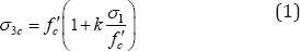
Where, k is a confinement factor (based on comparisons with the experimental punching program, Newhook [10] determined that a value of k=10 was appropriate for the bridge deck application).
Employing the equilibrium conditions and
relationships described above, the forces and displacement can be
resolved for a given value of applied load P. A complete description of
this mathematical formulation is found in Newhook [10]. In addressing the similar problem of the punching of a column slab connection, K & N [9]
established empirical criteria for punching failure which was adopted
by the authors for bridge deck slab punching. When the circumferential
strain at the top surface of the slab close to the loaded area reaches a
critical value, ϵ ct =0.0019, failure occurs. This value
corresponds to the value of strain at the maximum uniaxial compressive
stress fc, and the commonly used value of ϵ ct =0.002 is
adopted. While K&N merely reported this value as an empirical
observation, the authors propose that this criterion also corresponds
well with the importance of the 3-dimensional confinement of the
concrete surrounding the loaded area. Once ϵ t equals 0.002,
the concrete response softens in that direction leading to a reduction
in the confining force, hence punching failure.
The authors also proposed a second parameter that is
also capable of initiating punching failure. The lateral restraint is
provided by transverse steel straps. The stress in the straps increases
with applied load. It is possible that the stress in the straps reaches
the yield stress of steel before failure of the concrete occurs. Once
the strap yields, it can no longer provide increasing restraint force
and hence the concrete will punch under a slight increase in applied
loading.
Comparison with experimental work
Comparisons were conducted between experimental failure loads and those predicted by the mechanics model Newhook & Mufti [1]. A partial listing of those comparisons is presented in Table 1.
Comparisons of the theoretical and experimental load- deflection and
load strap strain results also showed very close agreement [10].
The theoretical model was used to analyze three half-scale tests reported by Mufti et al. [2] and Newhook [10], a deck test on a skew bridge reported by Bakht & Agarwal [11] and full scale testing reported by Thorburn & Mufti [12] and Newhook & Mufti [13].
The experimental deck slabs failed in punching shear and a comparison
of theoretical versus experimental failure load is presented in Table 1.
The comparison reveals that the mathematical model can predict within
reasonable accuracy the punching failure load of internally restrained
bridge deck slabs (Figure 4).


Using the procedure described above, a load deflection curve is constructed for half scale Test No. 5 from Table 1.
A small slab displacement is assumed and the associated value of
applied is load determined along with strap strain and concrete strain
values. If the failure condition is not satisfied, an increment of
deflection is assumed and new values determined Newhook [10,14].
This process is repeated until a failure condition is met. Using the
values of displacement and load, the theoretical curve shown in Figure 4
is produced. While the experimental curve the theoretical curve though
smooth is in good agreement with the observed deflections. The model is
reliable in predicting the order of the magnitude of deflection. The
experimental deck deflections at ultimate for the tests in Table 1 are compared with theoretical deflections in Table 2. The comparison reveals very close correlation providing further support for the validity of the mechanics model(Table 2)

Based on the successful development of this model,
the following parameters were confirmed as necessary to properly predict
the bridge deck behaviour under wheel load including prediction of
ultimate load: deck thickness, girder spacing, strap geometry (restraint
stiffness), concrete strength and strap modulus. In addition, strain
limits in the strap material and the concrete could be used to define
ultimate limit state.
Non-Linear Finite Element Modelling Studies
The initial investigation of externally reinforced bridge deck behaviour was conducted by Wegner and Mufti [15] who attempted to use finite element modelling to replicate the behaviour of the experimental model [2] listed as Test 3 and 4 in Table 1.
The commercially available program ADINA (ADINA R&D Inc. 1987) was
chosen, since it incorporated a sophisticated tri-axial material model
for plain concrete. Specifics of the model and analysis details are
reported elsewhere [15,16].
While Wegner and Mufti were able to model the behaviour of one specific
test, they concluded that this early finite element modelling attempt
was very sensitive to a number of parameters and that extensive
calibration with known results and modelling iterations would be
required to fine-tune the numerical procedures for a particular
application.
The Wegner and Mufti finite element study was
conducted prior to the development of the analytical model described in
Section 3. This model indicated clearly that for a commercial program to
be used successfully the K&N strain limit failure criteria must be
used. Hassan et al. [17]
conducted finite element analysis of an internally restrained concrete
bridge deck slab subjected to wheel loads using the "Anatech Concrete
Analysis Program" (ANACAP, Version 2.1) and defining failure as the load
at which the K&N failure criteria is met. One-half of a bridge deck
slab was modelled using 20-node brick elements. The slab thickness was
divided into three layers. The mesh dimensions used in modeling the deck
slab are given in Figure 5.
The reinforcement was modelled as individual sub-elements within the
concrete elements. Rebar sub-element stiffnesses were superimposed on
the concrete element stiffness in which the rebar resides. A complete
description of the modeling can be found in Hassan et al. [17] (Figure 5).


Hassan et al. [17]
modeled the punching behaviour of a full- scale experimental model of a
concrete deck slab on two steel girders tested by Khanna et al. [5].
The experimental model had four segments (Segments A through D) in
which the internal reinforcement configuration was varied. Segment A had
a top and bottom grid of orthogonal reinforcement, typical of current
design practice, and Segment C had just bottom transverse bars. The
comparison of the ANACAP theoretical results with the experimental
load-deflection results for these two segments are presented in Figure 6a and 6b,
respectively. For failure prediction, use of the K&N criteria was
critical. With this failure modeling approach, the FEM model proved to
be far more robust than the model used previously by Wegner & Mufti [14].
Furthermore, the study confirmed that the presence of top reinforcement
in bridge deck slabs has a negligible effect on punching shear capacity
(Figure 6a & 6b).
Specialized Non-Linear Fem For Bridge Deck Slabs - Fempunch
The successful use of the K&N failure criteria
with a commercial FEM program led to the development of a specialized
FEM program for non-linear analysis of externally restrained concrete
slab on girder bridges, FEMPUNCH. The program has several features which
facilitate the pre-processing and input of bridge geometry. It permits
the input of values for the lateral restraint of the straps and includes
an orthotropic material model for concrete as well as permits concrete
cracking and strain softening and models the benefits of 3-dimensional
confinement. It includes the limiting strain proposed by K&N as the
failure criteria. The concrete is modelled using a 20-node isoparamteric
brick element and the girders are modelled using 2-dimensional beam
elements.
FEMPUNCH theory and program
Complete details on modeling assumptions and parameters can be found in Desai et al. [18].
The following assumptions and simplifications have been incorporated into FEMPUNCH:
I. The stiffness of straps is smeared across the length of the girders.
II. Lateral stiffness of the supporting girders is considered to be uniform across the length of the girder.
III. The girders are unyielding in the vertical direction, a simplification that can be remedied easily.
IV. Concrete is modelled as an orthotropic material
with the direction of orthotropy being defined by the principal stress
directions.
V. Cracking can occur in three orthogonal directions at an integration point used in the formation of finite element equations.
VI. If cracking occurs at an integration point, it is
modelled through an adjustment of material properties by considering
cracking as a smeared band of cracks.
VII. Strain softening occurs from compression crushing failure to the ultimate strain, at which the concrete fails completely.
VIII. The tensile cracking failure and the concrete crushing failures occur along the principal direction
IX. Load increases monotonically, leading to failure
An isoparametric, 20-node solid brick element has
been used in the program to model a bridge deck. At each node, three
translational degrees of freedom (u, v and w) are considered. Details of
the shape functions and formulation of element level matrices can be
found in the literature.
Only one element has been considered in the thickness
direction on the basis of the finite element work done by Wegner &
Mufti [15].
On the other hand, the number of elements in the longitudinal and the
transverse direction is chosen such that the aspect ratio is nearly one.
On the basis of the average thickness, the program would select the
number of elements automatically between two adjacent sections. However,
a user can override this option and feedin the information explicitly.
Modelling of concrete
The 3-dimensional constitutive relations for concrete
have been derived from an equivalent, uniaxial constitutive relation,
which can be determined experimentally. The uniaxial stress- strain
curve has been employed in the program to calculate the tangent modulus.
The stress-strain curve for the concrete has been described by the Saenz's equation [18].
While other 3-dimensional concrete models exist, Saenz's model was
selected as it was found to be easier to program and provided equally
accurate results. It also avoided singularity problems in the solution
process encountered by Wegner & Mufti [15].
Modelling of crack
Tensile failure would occur in concrete when the tensile stress in the principal direction exceeds the tensile strength, a f, of concrete. The presence of a crack at an integration point is modelled by modifying the constitutive matrix [18]. When a crack forms, the normal as well as the shear stiffnesses reduce. Consider for illustration that σp1 exceeds σf.
Solution procedure
The ensuing system level equations are solved in the
Lagrangian coordinate system using Newton-Raphson procedure. In-core
solution technique has been used to expedite computations. The loads are
applied incrementally and iterations are performed per load increment
until the solution converges. The incremental displacements and stresses
areadded to the values from previous load increments to get the total
displacements and stresses. The numerical solution iscontinued until
failure occurs.
Comparison with internally restrained deck slab results
The internally restrained deck slab considered by Wegner & Mufti [15] (Figure 7)
has been analyzed using program FEMPUNCH. The load versus deflection
under the wheel load results obtained from program FEMPUNCH have been
compared with the experimental data, as well as results from the ADINA
analyses and results from program PUNCH [14]. It can be seen in Figure 8 that the results from program FEMPUNCH match reasonably well with the experimental data at failure (Figure 7 & 8).


This specialized finite element program incorporates
behaviour characteristics and failure criteria developed in the
analytical model of Section 3, it also provides several key
improvements:
a) Both right bridges and skew bridges can be analyzed;
b) The stiffness of the bridge girders can be modelled;
c) The influence of the global stiffness of the concrete deck outside the punch zone can be included; and
d) The influence of the wheel position relative to the planar geometry of the deck can be modelled.
Further investigations by Klowak et al. [19] demonstrated that the FEMPUNCH program can also be used to predict the response of deck cantilevers to wheel loads.
Conclusion
This paper presents a brief overview of the authors'
investigations into modeling the non-linear behaviour and failure of
concrete slab on girder bridges to supplement the extensive experimental
work in this area. Analytical and specialized finite element tools have
been presented. In developing these models, the use of the K&N
failure criteria was a key consideration in achieving correlation with
experimental results. Both models also allow for the development of a
load versus deflection curve for the entire loading not just a
prediction of ultimate load. Hence the models, and in particular the
finite element, will permit engineers to study the impact of various
geometry and material parameters on the behaviour of the deck system.
These parameters, in general order of greatest impact on ultimate load,
are:
a. Stiffness of the external restraint to the deck including straps and girders;
b. Deck thickness;
c. Girder spacing;
d. Strap material properties; and
e. Concrete strength.
The modeling work also shows that the punching
strength of the concrete deck slab cannot be considered a function of
just the concrete slab thickness and compressive strength alone but is a
property of the entire deck system including the girders and any other
means of lateral restraint, in the case external straps.
The punching strength of a concrete slab on girder
bridge deck subjected to wheel loads represents a complex problem
including both material and geometric non-linearities. To date, no
simplified formula has been able to capture the impact of all the
parameters discussed in this paper. It is believed that the research
presented in this paper will be of assistance to engineers seeking to
implement more rigorous solutions and to better understand the
influenceof their design choices on the performance of this bridge deck
system.
Acknowledgement
The authors acknowledge the contributions to modeling
and understanding bridge deck behaviour by the many graduate students
and research assistants whose published work is cited herein. The
authors also acknowledge the long standing collaboration with our
colleague Dr. Baidar Bakht who initially requested that we develop a
theoretical model to help understand the behaviour observed during
experimental work and who has continued to participate in the solutions.
For More Open Access Journals Please Click on: Juniper Publishers
Fore More Articles Please Visit: Civil Engineering Research Journal
Fore More Articles Please Visit: Civil Engineering Research Journal


Comments
Post a Comment