Vertical Flexibility in Isolation Systems- Juniper Publishers
Juniper Publishers- Journal of Civil Engineering
Abstract
This paper will review the history of
three-dimensional (3-D) seismic isolation, its implementation and its
drawbacks. It will cover the theoretical analysis of the rigid block on
springs and the circumstances under which the various motions are and
are not uncoupled. We will also review the records from a building with a
3-D isolation system that was impacted by fairly severe earthquake
action. This review suggests that the search for full 3-D isolation is
unlikely to be successful.
Introduction
While seismic isolation has been well accepted and
widely used for over thirty years, it has been horizontal isolation that
has predominated. The search for full 3-D seismic isolation has been
the holy grail of research for all of these thirty years. It was
originally assumed that they could be achieved by use of low shape
factor elastomeric bearings that is bearings with thick rubber layers
that provide a low vertical stiffness in concert with low horizontal
stiffness. One of the earliest applications of low shape factor bearings
was a research laboratory building constructed by the Kajima
Construction company in 1987 as both a demonstration building and as a
research facility [1]. The isolation system for the building was
made up of eighteen laminated natural rubber bearings with a shape
factor of 5.2 and several hysteretic (steel rod) dampers plus oil
dampers. The design frequencies were 0.5Hz horizontally and 5Hz
vertically The system was designed to provide 3-D seismic isolation and
also since the building housed an acoustic laboratory, to filter out
ground-borne vibrations, which it was shown to do very effectively. The
bearings were supported on steel boxes to allow for adjustments for
creep effects, which may be anticipated in low shape factor bearings
using filled natural rubber.
An experimental research program on low shape factor
natural rubber was carried out around the same time at the Earthquake
Simulator Laboratory of University of California, Berkeley Earthquake
Engineering Research Center (EERC). The purpose of this research program
was to study the mechanical characteristics of low shape factor
bearings intended to be for a then new type of liquid metal reactor
named SAFR designed by Rockwell International. The reactor module was to
be shop- fabricated and shipped to the site. Maximum horizontal and
vertical accelerations of 0.3g were specified and to allow siting in
highly seismic regions, it was decided to isolate the plant with a 3-D
isolation system using low shape factor bearings in this case with a
shape factor of 2.5. A very extensive test program on full size and
scaled bearings was carried out for the SAFR program with results
reported in EERC reports and papers (for example EERC 89/13) [2].
It was intended to use the large shaking table at the Earthquake
Simulator Laboratory to study the dynamics of a model of the reactor
building on these bearings but the SAFR program was shut down before
that could be done.
Although the Kajima project and the SAFR test program
seemed to be positive to the idea of using elastomeric bearings for 3-D
isolation, further efforts involved other approaches such as steel
springs and combined systems. The steel spring approach will be covered
in detail in later sections. The combined systems have very
sophisticated elements such as air springs developed by the Japanese
nuclear industry. Because of their complications and expense, these
systems have not been accepted for civil construction and the search for
a practical and inexpensive system continues. In this paper we will
explore the dynamics of the 3-D isolation system to highlight the
dilemma faced by the designers of these systems and to look at how, at
least in one system they respond to actual earthquake attack.
Isolation Systems with Vertical Flexibility
In most cases, isolation systems have only been
considered for horizontal isolation that the vertical flexibility of the
system is negligible. However, there are systems that can have a low
vertical stiffness comparable to the horizontal stiffness. There are
also situations where vertical isolation is considered to be essential.
If the vertical input to be eliminated is ambient ground vibration, the
natural rubber isolation system can provide this but if the vertical
input is seismic, the situation becomes considerably more complicated.
Nevertheless, rubber bearings and steel coil springs have been used in
an attempt to provide both vertical and horizontal isolation in a single
system. In an early example of a rubber isolation system to protect a
structure from earthquakes was in 1969 for an elementary school in
Skopje, Former Yugoslavia Republic of Macedonia. The Pestalozzi School, a
3-story concrete structure designed and built by Swiss engineers (Figure 1), is isolated by a system which was known at the time as the Swiss Full Base Isolation-3D (FBI-3D) System [3,4].


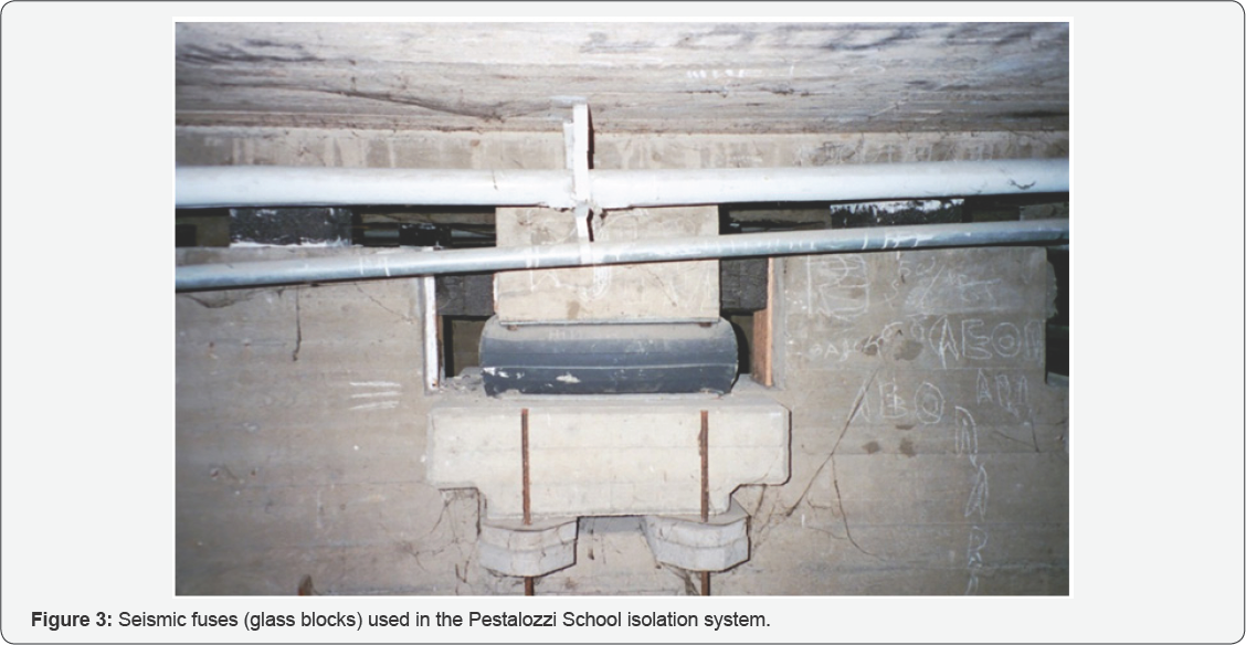
Unlike more recently developed rubber bearings, the rubber blocks used here (Figure 2) are completely unreinforced so that the weight of the building causes them to bulge sideways. Glass blocks (Figure 3)
acting as seismic fuses are intended to break when the seismic loading
exceeds a certain threshold. Because the vertical and horizontal
stiffnesses of the system are about the same, the building will bounce
and rock backwards and forwards in an earthquake but this was the
intention of the inventor as implied by the name.
These bearings were designed when the technology for
reinforcing rubber blocks with steel plates, as in bridge bearings was
not highly developed nor widely known, and it is unlikely that this
approach will be used again. It is worth noting that the original set of
rubber bearings was replaced in 2008 by more conventional modern steel
reinforced bearings under a contract from the NATO Science for Peace
Program. The details of the program to produce and to replace the old
isolators with the new isolators is provided in two publications [5,6].
The GERB system is based on steel springs with
viscous dampers and is intended for simultaneous vertical and horizontal
isolation. It was developed originally for the vibration isolation of
power plant turbine generating equipment. It uses large helical steel
springs that are flexible both horizontally and vertically. The vertical
frequency may be around 3-5 times the horizontal frequency. The steel
springs are completely without damping and the system is always used in
conjunction with the GERB Viscodamper. As in all 3-D systems, there is
very strong coupling between horizontal motion and rocking motion
because the center of gravity of the isolated structure is above the
center of stiffness of the isolation system. This type of system becomes
practical as a seismic protection approach only in situations where the
center of gravity and the center of stiffness are at the same level
such as a reactor vessel in a nuclear power plant, for example.

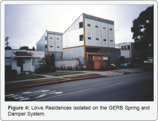
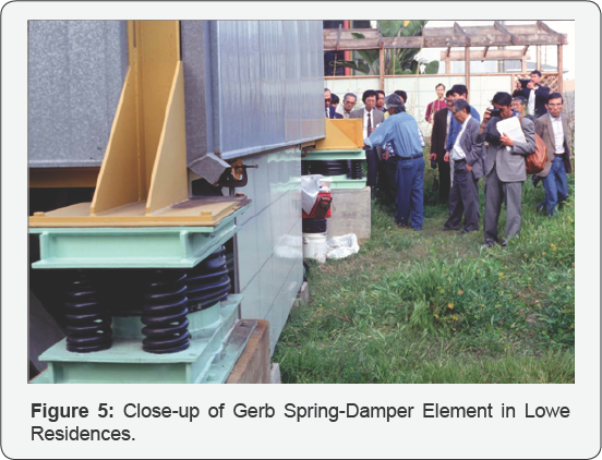
The system has been tested on the shake table at Skopje, Macedonia [7], and has been implemented in Lowe Residences, two steel frame houses in Santa Monica, California (Figure 4).
Each building is supported at its corners by GERB helical springs and
viscous dashpots. A single spring damper unit at a corner of one of the
buildings is shown in Figure 5.
Additional springs are distributed around the building perimeters.
These houses were strongly affected by the 1994 Northridge earthquake.
Their response was monitored by strong motion instruments and the
measured response, described in more detail later, revealed that the
isolation system was not very effective in reducing the accelerations in
these buildings most likely due to the rocking motion.

Dynamics of a Rigid Block on Springs
A rigid block of mass M and moment of inertia I is supported by two springs with stiffnesses k1x,k1z and k2x,k2zas shown in Figure 6.

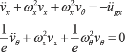
The three equations of motion of the block in terms of relative displacements at the center of mass vx,vz and the rotation of the block θ are
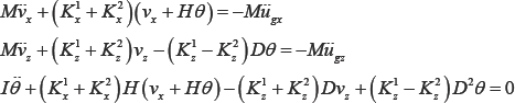
For an isolated system it is most likely that K = K2 and K1 = K2 from which we define the three overall stiffnesses
We now define the rotation as an equivalent displacement vθ = Hdand define the radius of inertia of the block R where I = MR2. The three nominal frequencies of the system are, 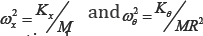 in terms of which the equations of
in terms of which the equations of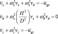
It is clear that in the case of a symmetric system
the vertical motion is uncoupled from the other two and can be treated
separately. The eigenvalues of the vector from the first two coupled equations denoted by
  and given by
  leads to eigenvalue frequencies w1andw2. The equations for the mode shapes corresponding to these frequencies are
from the first two coupled equations denoted by and given by leads to eigenvalue frequencies w1andw2. The equations for the mode shapes corresponding to these frequencies are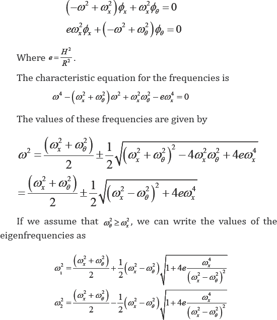
Substituting these values back into the equations for , gives the solution for ø1ø2 and f. gives the solution forø1and ø2
.To verify that these mode shapes satisfy the requirement of
orthogonality, it is necessary to rewrite the reduced equations of
motion in such a way that both the reduced mass matrix and the reduced
stiffness matrix are symmetric, that is
and in this case the reduced mass matrix  with the modes orthogonal with respect to this matrix. They can then
be used as a basis for a dynamic analysis by expressing the displacement
vector
with the modes orthogonal with respect to this matrix. They can then
be used as a basis for a dynamic analysis by expressing the displacement
vector 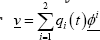 in terms of which the above equation becomes
with the modes orthogonal with respect to this matrix. They can then
be used as a basis for a dynamic analysis by expressing the displacement
vector in terms of which the above equation becomes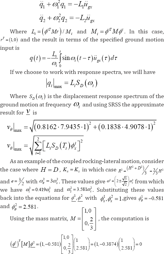
Thus showing the mode shapes are orthogonal and can
be used as basis for dynamic calculations. For this example, we have M1 =
1.2251, M 2 = 5.441 and L = 0.8162, L2
= 0.1838. To determine the dynamic response it is necessary to define
the uncoupled horizontal period which here we will take as one second.
From this, the uncoupled horizontal frequency is rad/sec and the
uncoupled rotational frequency is me=-/32;t rad/sec. The resulting periods of the coupled system are T = 1.545 sec and T2
0528 sec showing that the horizontal period is lengthened and the
rocking period is reduced by the coupling between the two components.
Taking as an example the Imperial Valley record from El Centro1940, the
response spectrum of which is shown below in Figure 7,
the estimates of the horizontal displacement and rotational
displacement (the corner horizontal displacement in addition to the
center of mass displacement) illustrate the fact that the rocking is a
very large part of the movement of the structer in the case.

The spectral acceleration values at the first and second mode periods are SA (T1 = 1.545) = 0.3403g and sa (T2 = 0.528) = 1.7978g. The spectral displacement corresponding to the first and second mode periods are sd (t1 = 1.545) = 7.9435 and SD (t2 = 0.528) = 4.9078. The peak response estimated using the response spectrum method can be determined by using
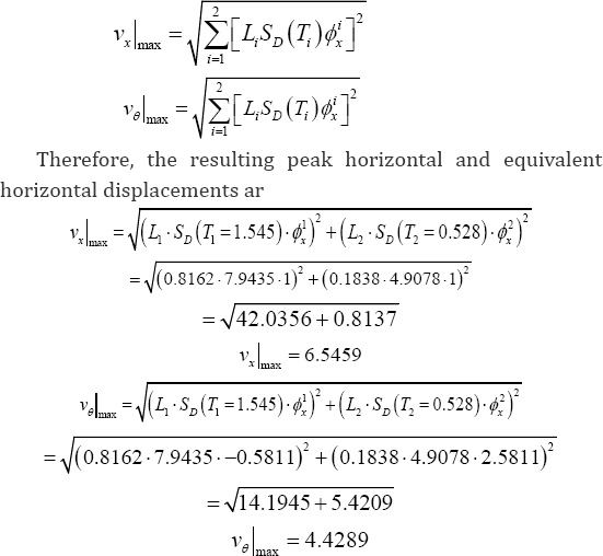
These results are in inches and ve is the additional displacement of the top right corner (beyond the center of mass displacement) in the x
direction showing that the influence of the rocking motion in an
example where the vertical stiffness of the isolation system is
comparable to its horizontal stiffness cannot be ignored. On the other
hand, we will show in the following that if the vertical stiffness is
much larger than the horizontal, the rocking can be ignored.
If we assume that ω≥o2 we can express the frequencies by
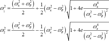
It is clear from these equations that if e = 0, i.e. H = 0 that the two eigenfrequences are ωx and zωg and that the equations of motion are uncoupled but there are other implications from the solutions. If mB > mx the second term within the square root becomes small and when it is expanded by binomial series we get
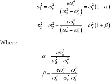
We define the ratio of the vertical and horizontal stiffnesses as 1 = KK and note that X can range up to around 1000 in high shape factor cases. Recalling that 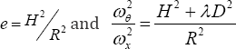 where
where we find that
wherewe find that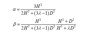
For example, if H=D and λ=100 then α=3/1+3α~~1/λand  showing that ω1 is almost the same ωx and ω2 is completely unchanged with this value of the ratio between the vertical and horizontal stiffnesses of the isolation system.
showing that ω1 is almost the same ωx and ω2 is completely unchanged with this value of the ratio between the vertical and horizontal stiffnesses of the isolation system.
The results for α and β show the
interaction is reduced with increasing vertical stiffness as compared to
horizontal stiffness but they also show that the ratio H/D can play a significant role. To illustrate the role of H/d which we denote byp p,
we consider the case where the nominal horizontal frequency is fixed so
that if the height of the building is increased with the width fixed,
the mass is increased at the same rate, as is the bearing horizontal
stiffness and the ratio of vertical stiffness to horizontal stiffness X remains constant. The question is: what level of A is needed to ensure that the two modal frequencies m and m2 are changed by the coupling from the nominal by less than a specified tolerance � (for examples=2%2)? It is clear that the most critical of the frequency shifts is a where
which leads to the rather surprising result that if the height to width ratio of the building is 10
and the tolerance on frequency change is 2% then bearing stiffness
ratio must be 5000. This is quite beyond the possibility of rubber
bearings showing that rocking is always going to be a problem in tall
structures. If the largest possible value of λis 1000 then the height
ratio for an ε of 2% is around 4.5.
To illustrate the effect of the height ratio on the
eigenfrequencies and the response for specific examples a number of
different heights with constant width but fixed horizontal nominal
frequency were studied using time history analysis of the record with
the response spectrum shown in Figure 7 and in Table 1.

In the system used to show the effect of the height
ratio, the ratio of the horizontal and vertical stiffnesses, here
defined by zxKK�= were varied from 1 to 500, and the nominal horizontal
period of the isolation system was set at 1 second for all height to
width ratios implying that the width D is held fixed and the mass M was
taken proportional to the height H. With this choice of stiffness's the
nominal rocking frequency give by
is constant with height, which is counter intuitive. The dynamic properties of this system are given in Table 2a-2c
where we see that the lowest frequency, that for horizontal, is very
much reduced as the height ratio increases but the rocking frequency is
only slightly modified (it is increased).


It is clear from these results that as the ratio of
the vertical to horizontal stiffness / increases that the changes in
frequencies of both the first horizontal mode and the rocking mode
become very minimal even for large values of the height ratio.
The response for the horizontal and rocking
displacements for the case where the horizontal and vertical stiffness's
of the system were the same (y = 1) was estimated by using time history computation with the unscaled El Centro 1940 record and are given in Table 3.

There is an unexpected result that both the horizontal displacement vx, the displacement of the center of mass and the rocking displacement V
, the additional displacement at the left hand corner of the block, are
maximized at the ratio of 5 but this is due to fact that the record has
very little content at the long periods implied by the combined system
frequencies for height ratios above 5. This would not happen for a
constant velocity design spectrum.
Measured Response of GERB System Building


The isolated structures closest to the epicenter of
the 1994 Northridge earthquake were two identical 3-story braced steel
frame residences in Santa Monica, California, located 22km from the
epicenter. Figure 4
shows an overall view of the residences; one of the structures is
instrumented by the United States Geological Survey (USGS). Each
building is supported at its corners by GERB helical springs and viscous
dashpots. Additional springs are distributed around the building
perimeters. The design frequencies of the isolation system were 2.5Hz
vertically and 1.4Hz in rocking (both directions). Relatively high
isolation frequencies were chosen with the intension of limiting the
structure displacements to 30mm horizontally and 20mm vertically.
Equivalent viscous damping on the order of 25% to 30% of critical was
anticipated from the dashpots, and the design anticipated that this
level of damping would be sufficient to suppress acceleration
amplifications due to resonance. Figure 8a-8g
show the recorded acceleration time histories with peaks at the level
below the isolators of 0.16g in the vertical direction, 0.40g in the
145-degree direction and 0.44g in the 235-degree direction.
Accelerations above the isolation system were generally larger with
increased high-frequency content; at the first level the horizontal
accelerations were 0.51g and 0.52g in the 145- and 235-degree directions
and at the third level 0.68g and 0.68g in these directions. The USGS
did prepare a digitized version of these records, but it did not include
the vertical component of the records above the isolation system that
were impossible to follow; furthermore, the high frequency content in
the horizontal records prevented accurate digitization. Using the FFT,
the responses above the isolation system show the dominant response was
strongly at one second period as shown in Figure 9a-9d. This is most likely to be the rocking frequency for the structure.
The vertical records inside the building are missing
from the USGS published results presumably because they could not be
digitized but the records from an earlier earthquake that affected the
buildings, the Big Bear Earthquake of 1992, have complete vertical
records at all three levels. Although small, the earthquake epicenter
was distant (132 km), the results for peak acceleration values were
quite revealing for this study since the in-structure vertical records
were readable. The measured input below the isolation was 11cm/sec/sec
vertical and 29 and 22cm/sec/sec in the 145- and 235-degree directions
respectively. At the first floor, these were 22, 32 and 22cm/sec/ sec.
At the third floor the records were 26, 41 and 24cm/sec/ sec. It seems
that the in-structure vertical and the 235 horizontal are about the same
as the horizontal input whereas the 145 horizontal is amplified. The
vertical at the two floors was much larger than the vertical under the
isolation suggesting that the building was rocking about the 235
direction and amplifying the vertical response.

It appears from both the records and from a survey of
the buildings performed after the earthquake that the isolation system
was not as effective as intended; several architectural and construction
details limited movement of the superstructure.
For example, slight damage was observed at locations
where steel girders from the isolated portion of the structure framed
into both a concrete footing and a masonry block wall attached to the
ground (Figure 10).
Also, a series of square glass blocks distributed around the perimeter
of the structures at the foundation level may have contributed to the
large amplifications of the vertical motion. The owner indicated that
these blocks were adjusted so that they would be damaged at increments
of vertical displacement; the rows of blocks adjusted to 12.5mm and 19mm
were broken, while the row of blocks adjusted to 25mm remained intact.
This is consistent with the design vertical displacements computed from
the acceleration records [8].
It is possible that pounding between these blocks and
the foundation of the structure may have led to the high-frequency
vertical acceleration spikes. This building has been the only
application of the 3-D isolation system to be impacted by an earthquake
and to have its response recorded. It has shown very clearly that these
systems cannot be used effectively for seismic protection of buildings
however useful they may be for vibration isolation.
Conclusion
This paper has covered the history of the search for
3-D seismic isolation in the form of systems using a single component.
While all successful isolation systems developed so far have provided
only horizontal isolation, the search for an inexpensive approach to a
3-D isolation system has been ongoing for several decades. Many
complicated multiple component systems have been developed, mainly for
sensitive internal equipment in buildings such as nuclear power plants
and chip manufacturing plants, these have proved to be extremely
expensive and unsuited for use in most civil structures.
We have shown examples of 3-D systems that have
actually been implemented in buildings and have outlined their
deficiencies. In the paper, the theoretical basis of the 3-D system has
been examined in detail and the cause of these deficiencies, namely the
presence of rocking modes has been illustrated. The level of relative
vertical flexibility for which a satisfactory performance can be
achieved is described. The most likely conclusion of this study is that
search for full 3-D seismic isolation has not yet been achieved.
For More Open Access Journals Please Click on: Juniper Publishers
Fore More Articles Please Visit: Civil Engineering Research Journal
Fore More Articles Please Visit: Civil Engineering Research Journal


Comments
Post a Comment