Further Thoughts on the Structural Efficiency of Suspension Bridges- Juniper Publishers
Juniper Publishers- Journal of Civil Engineering

Abstract
Recent proposals for very long span bridges, such as
those proposed for the Straights of Messina and Gibraltar, have reopened
the questions as to which forms provide feasible solutions and within
those forms what particular geometries will result in the most efficient
solution - in terms of both material volume and cost? While these
questions can now be approached using sophisticated optimization
software it would seem that simple engineering reasoning still has much
to offer. The following rehearses some simple analytical approaches to
the question of assessing the relative efficiencies of different bridge
geometries considered in an earlier paper and uses this approach to
widen the discussion and address the issues of what parametric choices
within each of these different geometric classes of bridge would provide
the most materially efficient solution.It compares the material
efficiency of the common forms of catenary-type and cable-stay
suspension bridges, and assesses the relative merits of the so called
harp and fan forms of cable-stay bridges. It also extends past analyses
to various classes of multi-pylon cable stay bridges and shows how these
relate to the theoretical optimal Mitchell structure. Finally, it
suggests that the simple physically based models developed in relation
to bridges might form a template for future conceptual design for which
computers can be relied upon to carry-out the detailing.
Keywords: Structural efficiency; Suspension bridges; Catenary
Background
Some years ago the author had occasion to ponder the
question as to which form of suspension bridge, the traditionally
preferred catenary-type or the increasingly popular cable- stayed,
provided the best solution for bridging large spans. This work, outlined
in Reference [1],
was undertaken while sailing up the River Seine on route to the
Mediterranean. At the time the Pont du Normandie had just been completed
and the wonderfully slender lines of its stiffening girder and cables
contrasted strongly, when viewed at an equal distance, to the stockier
cables and girder of the Tancarville catenary-type bridge having a very
similar span but completed some 35 years earlier. Having to complete the
first leg of this sail to Rouen on a single tide I found myself with
time on my hands to attempt to prove that the more daring slenderness of
the new Pont du Normandie must result from the of use of higher
strength steels. After all for a uniformly distributed load the
parabolic form of the Tancarville bridge, in following the shape of the
moment distribution, must surely provide the most efficient solution? Or
so I thought. Because the results of these musings proved so counter to
my intuitive understanding the results were sent in the form of a
letter to the editor of The Structural Engineer; to my surprise this was
subsequently published as a feature article [1] which attracted an agreeable range of enlightening discussion [2].
Subsequently the methodology that had been developed formed the basis of a teaching module [3]
encouraging students to use similarly simple calculations to make
rational decisions for more general forms of structure. This encouraged
the use of non-computer based analyses to allow assessment of the
structural forms most likely to provide materially efficient solutions
for a given function and which would not. And inevitably such
comparisons allowed consideration of the extent to which aesthetics
should or should not be separated from issues of material and mechanical
efficiency and cost.
For the classes of bridge structure considered in the
original article the primary load paths involved membrane behaviour
with individual members carrying their loads through axial tensions and
compressions. In contrast, many recently proposed bridges involve
primary load paths requiring the development of bending action. To be
able to make meaningful comparisons of their relative efficiencies it
was necessary, as part of the teaching course developed, to extend the
original methodology to allow treatment of structures for which bending
is involved in the primary load paths. In this regard the bridges of
Calatrava [4]
made instructive case studies. And having a simple treatment of bridges
involving both membrane and bending actions allowed the approach to be
extended to the treatment of wider classes of buildings and structures.
This in turn enabled consideration of the structural efficiencies of
some of the new styles of building favoured for example by the so called
High Tech architecture movement [5]
relative to more conventional buildings. Like many of the more recent
bridge forms these examples from recent trends in building provided
equally compelling illustrations of how the choice of an inappropriate
structural form can lead to very inefficient use of material and
spiraling costs - see for example Refs [6,7].
And of course this provided the material for much wider discussion of
whether aesthetics and form in structures should follow material and
mechanical efficiency, or whether they can be considered separately. Or
whether, as Guest, Draper and Billing to night put it, whether a
particular structure embodies "structural art" or merely "art in
structures" [7].
Recent efforts to revive the proposals for bridges across the Straights of Messina and Gibraltar [8,9]
have reopened questions relating to the relative efficiencies of
various bridge forms. In the following a brief summary is given of the
method developed to assess relative efficiencies of competing structural
forms in which the primary load paths do not involve bending. This will
be used to illustrate the main conclusions on the relative efficiencies
of the parabolic cable and cable stay suspension bridges contained in
Refs [1,2].
This is followed by some further calculations which illustrate the
relative efficiencies of the so called harp and fan forms of cable-stay
bridges. And because they have been proposed as possible solutions for
longer span bridges a final section will deal with cable stay bridges
having multiple pylon supports. Increasing the number of multiple pylons
will be shown to eventually converge to the "optimum" Mitchell
structure [10].
Relative to their more conventional counterparts these will be shown to
often embody very efficient use of material. Finally, brief
consideration will be given to the wider socio-economic factors at work
in many recent developments in structural engineering and how these fit
into a global agenda where waste and profligacy should be and are
increasingly challenged.
Basis for Calculating Material Efficiency
Member volumes for axially loaded members
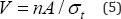
A member i carrying a tensile axial force Fti constructed from a material having a characteristic material tensile strength
σt will require a cross section area  If the force remains constant over the length li of the member i then the volume of material required to carry this tensile force will be Vi = Ai .li or
If the force remains constant over the length li of the member i then the volume of material required to carry this tensile force will be Vi = Ai .li or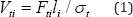
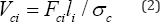
In a similar way the volume of a member i carrying a constant compressive force Fci having a characteristic compressive strength σc will be
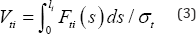
In a situation such as for the cable of a catenary
type suspension bridge the axial force will vary over its length so that
eq. (1) would become
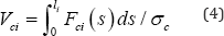
While for the volume of a compression arch would similarly
be
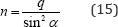
In a related way a flat plate of area A carrying a uniaxial stress resultant n will require a thickness of t = n /σt so that the volume required would be given by
In many cases where cable nets are involved it will
be convenient to replace the individual cables with an equivalent
continuous thin membrane plate having the thickness of the smeared out
areas of the cables allowing the total cable volumes to be expressed in
the form of eq. (5).

For a structure consisting of an assemblage of m individual members, such as that shown in Figure 1, the total volume of material required will be
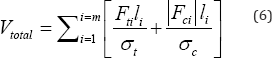
Where, in line with current terminology forces Fi will be taken as positive when tensile Fti and negative in compression Fci
Maxwell's Lemma: In the following it will be helpful to recall one of Maxwell's lesser known lemma, which in paraphrase states that:
"any structure made up of assemblage of members i carrying axial forces Fi that are in a state of overall equilibrium with applied and reactive external forces Pj
which are fixed in both position and orientation, will have the
algebraic sum of the product of the axial forces and their lengths equal
to a constant"
In terms of the present notation this lemma could be written as
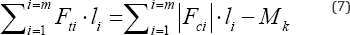
Where Mk is the Maxwell constant and again forces Fi
will be taken as positive when tensile and negative in compression. It
does not matter what form the structure takes, this statement remains
true. The proof of this was elegantly presented by Maxwell [11] but because it was seemingly not sufficiently well recognized was given new life in Ref. [12].
Perhaps the simplest method of proving this lemma is the following;
this is given since it will provide a simple conceptual way of
evaluating the Maxwell constant Mk .
Consider the arbitrary if somewhat contrary structure of Figure 1,
and imagine that it is uniformly contracted down until it becomes
infinitesimally small and lies at the origin point O. In doing so the
axial forces Fi will have undergone a relative movement of li
with the compressive forces doing positive work on account of their
relative deformations being in the same sense as the forces while the
tensile forces will do negative work. With the work done by the internal
forces equaling the work done by the external forces, the Maxwell
constant Mk in eq. (7) can be seen to represent the
positive work done by the external forces in undergoing the deformation
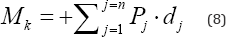
required for them to be acting at the point O . With dj representing the distance from the original position of the external force component Pj to the point on the line of action Pj of from which a normal drawn from this line of action of Pj passes through the point O , then the Maxwell constant is given by
Reflecting the convention of his time, Maxwell
adopted the convention of compression being positive. Were this the
present case there would be no negative sign on the right side of eq.
(7). It is understood that dj in eq. (8) are positive when dj is in the positive direction of the external force Pj.
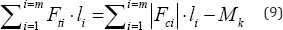
Allowing the total material volume of eq. (6) to be rewritten in terms of just the tension members
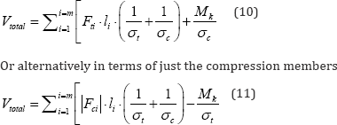
Provided the Maxwell Mk constant is
known the use of Maxwell's lemma allows the work required to calculate
the volumes of primary elements in a structure to be halved. For the
sake of brevity this will be the approach adopted in the following.
However, as previously illustrated [1,2]
it may be prudent to calculate the volumes of both the tension members
and the compression members and use the Maxwell lemma of eq. (6) as a
check on the voracity of the calculations.
Applications to conventional suspension bridges
To eliminate the difficulties of comparing relative
efficiencies when there are different requirements for the foundations,
previous comparisons assumed that for both the catenary and harp
cable-stay bridges the end supports needed to develop the horizontal
thrust  conventionally required of the catenary- type suspension bridge. This
meant that for the cable-stay bridge the deck needed to develop both
tension and compression in equal measure. Because this is perhaps
unrealistic in terms of conventional practice for cable stay bridges the
calculations will here be repeated under the assumption that there is
no horizontal thrust developed at the end supports for all the cases to
be considered. While this requires a compression force to be transmitted
through the deck of the catenary-type suspension bridge, it has the
merit of eliminating the need for horizontal forces at the end supports.
Although not the usual practice for catenary-type suspension bridges
this assumption provides another perfectly valid way of comparing the
relative efficiencies when using conventional practice for cable-stay
type bridges.
conventionally required of the catenary- type suspension bridge. This
meant that for the cable-stay bridge the deck needed to develop both
tension and compression in equal measure. Because this is perhaps
unrealistic in terms of conventional practice for cable stay bridges the
calculations will here be repeated under the assumption that there is
no horizontal thrust developed at the end supports for all the cases to
be considered. While this requires a compression force to be transmitted
through the deck of the catenary-type suspension bridge, it has the
merit of eliminating the need for horizontal forces at the end supports.
Although not the usual practice for catenary-type suspension bridges
this assumption provides another perfectly valid way of comparing the
relative efficiencies when using conventional practice for cable-stay
type bridges.Catenary-type suspension bridge
Figure 2a highlights the equivalent of a typical span l
of a multi-span catenary-type suspension bridge (it being understood
that the term catenary is here being used loosely to describe what of
course would normally be a second order parabolic cable) having pylons
of height h above deck and carrying an assumed uniformly distributed load q
. In this case we could integrate the volume of the cable to account
for its variable tension force and similarly integrate the volume of
material required for the hangers. In this case this would be a rather
long winded process, so instead the consideration of material volumes
will be approached via the compression members. There are just two
compression members each having a constant compressive force. The pylon
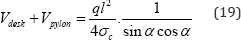
carries a constant compression of ql while the deck transmits a constant compression of  . Hence the sum of the compression forces times their respective lengths will in this case be given by
. Hence the sum of the compression forces times their respective lengths will in this case be given by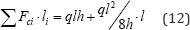

Because there are no externally applied horizontal forces and the applied downward vertical force of ql
is at the same vertical elevation as the equal and opposite reactive
force, the Maxwell constant will for this system be zero, implying that
the total material volume could be written
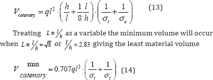
As shown in Figure 2b, it is noteworthy that the value of
associated with the minimum primary structural material volume does not
depend upon the choice of characteristic tensile and compressive
stresses (σt,σc)although of course this is not the case for total material volume required.
of
associated with the minimum primary structural material volume does not
depend upon the choice of characteristic tensile and compressive
stresses (σt,σc)although of course this is not the case for total material volume required.
of
associated with the minimum primary structural material volume does not
depend upon the choice of characteristic tensile and compressive
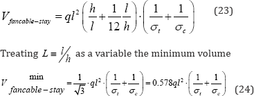
stresses (σt,σc)although of course this is not the case for total material volume required.Harp-type cable-stay bridge
Consider a typical span l of a multi-span harp-type cable- stay bridge having pylons of height h above deck level, as shown in Figure 3a, subject to a uniformly distributed load of intensity q
over each of its spans. Instead of considering individual cables it is
perhaps more convenient to assume the cable net acts as if it is a
continuous thin membrane plate having a maximum principal membrane
stress resultant n in the direction of the cables and a minor
principal membrane stress of zero in the direction normal to the cables.
Vertical equilibrium of a typical element from this continuous plate
shown in Figure 3b requires

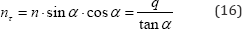
Where, α is the inclination of the cables. Horizontal equilibrium of this same typical cable element shown in Figure 3b will be provided by the horizontal shear stress resultant nτ where
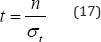
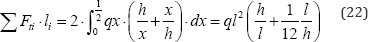
The volume of the tensile steel required for the cable net may then be determined by multiplying the thickness t required of the equivalent membrane plate of the cable net, given as
by the vertically projected area 0.5l h of the cable net, which on account of tana  gives a total tensile steel volume of
gives a total tensile steel volume of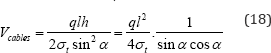
In eq. (18) the expression when the characteristic tension stress αt
is removed represent the sum of the product of the tensile forces times
the lengths of the members. Since for this structure the applied deck
force of ql is at the same level as the reactive support force ql , and there are no other external forces, the Maxwell constant is again zero, so that Mk = 0. It follows from Maxwell's lemma that
The total material volume required to carry the primary loads for the harp cable-stay is therefore
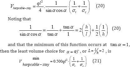
As shown in Figure 3c
& 3d, it is noteworthy that this least material volume for the
harp-type cable stay requires around 30% less material than the
equivalent catenary bridge of eq. (14).
Fan-type cable-staybridge

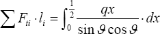
Which on account of eq. (20a) and the consideration that tanϑ=h/x may be written for a typical span l
Allowing the total material volume to be written
will occur when 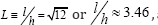 as depicted in Figure 4c & 4d. This form of fan-type cable-stay bridge is therefore less efficient than the least weight harp-type cable-stay of Figure 3,
requiring around 15% more primary material volume, but more efficient
than the least weight catenary-type suspension bridge of Figure 2,
requiring 18% less material. However, it should be recalled that the
catenary-type suspension bridge considered here requires the horizontal
component of tension force in the cables to be equilibrated through the
development of an equal and opposite compression force over the entire
length of the stiffening girder. This is not of course the usual
practice in catenary-type suspension bridges. The more representative
case of the horizontal thrust being equilibrated by end supports will be
treated in a later section.
as depicted in Figure 4c & 4d. This form of fan-type cable-stay bridge is therefore less efficient than the least weight harp-type cable-stay of Figure 3,
requiring around 15% more primary material volume, but more efficient
than the least weight catenary-type suspension bridge of Figure 2,
requiring 18% less material. However, it should be recalled that the
catenary-type suspension bridge considered here requires the horizontal
component of tension force in the cables to be equilibrated through the
development of an equal and opposite compression force over the entire
length of the stiffening girder. This is not of course the usual
practice in catenary-type suspension bridges. The more representative
case of the horizontal thrust being equilibrated by end supports will be
treated in a later section.Applications to non-conventional suspension bridges
There have been suggestions that instead of just a
single pylon at each support there may be advantage in using a number of
radially directed pylons. Because they are a step towards the optimal
Mitchell-type structure (10) it is certainly probable that these
multi-pylon structures would have advantages over the single pylon case.
In the following a number of alternatives are considered and shown to
converge to the Mitchell optimum structure as the number of pylons
increases. Consideration of their practicality will be deferred to a
later section.
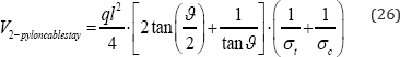
Two pylon cable-stay
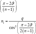
As a first example of a multi-pylon solution consider the case shown in Figure 5a.
Taking as an illustrative example the pylons having length equal to the
half span of the deck, but allowing the inclination of the pylon to be
variable at ϑ , implies that the inclination of the cables at the
deck are (90-ϑ/2) so that the stress resultant n1 equivalent to the
action of the cables in the lower cable net is

Resolving the forces normal to the inclined pylon requires that the stress resultant n2 equivalent to the action of the cables in the upper cable net be given by

With the area of the lower and upper cable nets being respectively
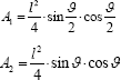
the total volume of tension steel in the 3 cable nets will be given by
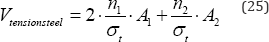
and on account of Maxwell's lemma the total volume of steel will be
For varying ϑ the total volumes of primary steel shown in Figure 5b & 5c can be seen to exhibit a minimum of
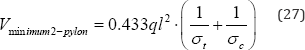

When ϑ = 60°. This represents a 13% reduction in primary structural material required compared with the harp cable stay of eq. (21).
Three-pylon cable-stay
As a second example of multi-pylon cable-stay consider the 3 pylon case of Figure 6
for which the inclined pylons are taken to have a variable inclination
of ϑ Again for illustrative purposes it is assumed that the pylon has
length equal to the half span of the deck making the inclination of the
cables at the deck again  , so that the stress resultant n1 equivalent to the action of the cables in the lower cable net is
, so that the stress resultant n1 equivalent to the action of the cables in the lower cable net is


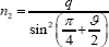
Resolving the forces normal to the inclined pylon requires that the stress resultant n2 equivalent to the action of the cables in the upper cable net be given by
With the area of the lower and upper cable nets case in this
being respectively
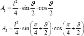
The total volume of tension steel in the 3 cable nets will be given by

and on account of Maxwell's lemma the total volume of steel will be
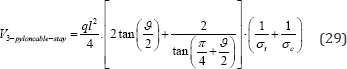
For varying ϑ the total volumes of primary steel shown in Figure 5c can be seen to exhibit a minimum of
When,ϑ = 45°. This represents a 17% reduction in
primary structural material required compared with the harp cable stay
of eq. (21).
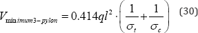
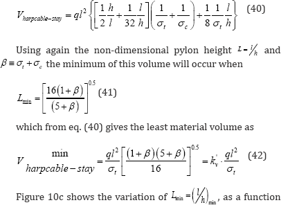
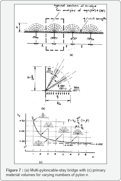
Multi-pylon cable-stay

It is generally the case for multi-pylon cable stay
bridges that the v least volume will be displayed when the pylons are
separated by equal angles. Adopting this a multi-pylon cable- stay
having n pylons shown in Figure 7a will have the first pylon. at an inclination angle of  the cables at the deck will be
  with the stress resultant n1 equivalent to the action of the cables in the lower cable net given by
the cables at the deck will be with the stress resultant n1 equivalent to the action of the cables in the lower cable net given by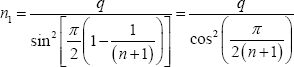
Resolving the forces normal to the inclined pylon
requires that the stress resultant equivalent to the action of the
cables in the next cable net must also be equal to n1 , so that all cable-nets have the same stress resultant n1 equivalent to the action of the cables.
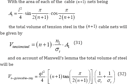
For varying n the total volumes of primary steel shown in Figure 7b & 7c can be seen to include the one, two, and three pylon cases considered separately in eq. (21), (27), (30). In the limit as n≚∞
This limiting case represents more than 21% reduction
in total primary structural material compared with the harp cable stay
of eq. (21). Furthermore, this limiting case which represents an
infinite number of concentric semi-circular members being intersected by
an infinite number of radial members is often referred to as the
"Mitchell optimum"[10].
Whether it is practical is of course another story. But in this context
the use of multiple pylons emanating from each of the support piers can
be viewed as an approach to this Mitchell optimum.
Hybrid cable-stay
As a variant on the multi-pylon solution for the
cable stay is the case where the radially emanating pylons are
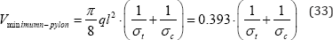
concentrated about the centre line of the support, as shown in Figure 8a. Adopting this hybrid multi-pylon cable-stay having n pylons shown in Figure 8a the lowest pylons will be taken to subtend an angle ϑ to the deck. Assuming pylons to be equally spaced the jangle between adjacent pylons will be L  I. Following the above analysis, for which the use Maxwell's lemma
allows the total volume to be inferred from just an analysis of the
volume required for the tension steel, the equivalent membrane stress
resultants in the two forms of cable net are
I. Following the above analysis, for which the use Maxwell's lemma
allows the total volume to be inferred from just an analysis of the
volume required for the tension steel, the equivalent membrane stress
resultants in the two forms of cable net are
I. Following the above analysis, for which the use Maxwell's lemma
allows the total volume to be inferred from just an analysis of the
volume required for the tension steel, the equivalent membrane stress
resultants in the two forms of cable net are
Where, n relates to the lower and larger cable net of Figure 8b, and n2 to any one of the smaller upper cable nets shown in detail in Figure 8c. With the respective areas of these two cable nets being
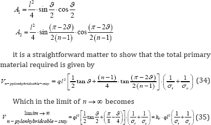
Figure 8d shows the variation of total primary material volume for varying ϑ reaching a minimum value of l/h»20 at ϑ =
0" (which is the condition for stationarity of eq. (34) and also of
course identical to the Mitchell optimum of eq. (33)and exhibiting a
very flat variation as ϑincreases. With the first pylon chosen to have
an inclination of 45" for example the total material volume would be
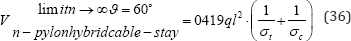
Which is just a little over 6% higher than the Mitchell optimum. Figure 8e shows for the case of ϑ =
45- the variation in the total material volumes required as the number
of pylons n for the hybrid case increases -note the minimum number for
this case would be n = 2 . Again, this variation shows very little change as n increases. For n=3 for example kv = 0.423 which is a little under 8% higher than the Mitchell optimum and around 15% lower than the harp cable-stay of eq. (21).
Suspension Bridges with Horizontal Foundation Thrust
Clearly the various possible bridge forms considered
above represent just a small sample of the possible designs for bridge
structures. One of the aims in presenting this limited range of
alternative designs is to demonstrate that simple hand calculations have
considerable merit in comparing the relative structural efficiencies of
various alternatives. The supports have been chosen to conform to those
typical of cable-stay bridges, in that there is no horizontal thrust
requirement at the end supports. To allow direct comparisons the
catenary type suspension bridge was also taken to have no horizontal
thrust requirement at its end supports, with the cable horizontal
tension being instead equilibrated by a compression force over the
entire length of the deck. This of course adds considerably to the total
structural volume required and perhaps misrepresents the merits of the
catenary-type suspension bridge relative to those of the various forms
of cable-stay bridges considered. The following makes similar
comparisons but with the horizontal thrust being provided by the end
supports; it is this situation that was described in Ref [1,2].
Catenary-Type Suspension Bridge with Horizontal Foundation Thrust
To represent conventional practice Figure 9 shows the same multi-span catenary-type bridge as that of Figure 2
with the difference that the horizontal thrust is now generated at the
end supports. For this situation considered in greater detail in Ref [1,2],
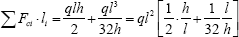
there is just one compression member - that of the pylon - so that for
the typical section of the bridge shown eq. (12) now becomes


In this case the Maxwell constant is  which represents the negative work done by the outward horizontal reaction of
  moving through the distance l
of the single span but in the opposite sense to the force. On the basis
of eq. (9) the sum of the products of the tension forces times their
lengths would for this case be
moving through the distance l
of the single span but in the opposite sense to the force. On the basis
of eq. (9) the sum of the products of the tension forces times their
lengths would for this case be
which represents the negative work done by the outward horizontal reaction of moving through the distance l
of the single span but in the opposite sense to the force. On the basis
of eq. (9) the sum of the products of the tension forces times their
lengths would for this case be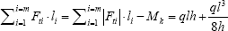
Notice that through the use of the Maxwell lemma it
is not here necessary to calculate separately the volumes of the tension
members, as was done in Ref. [1]. It follows that the total material volume will be given by
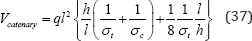
Introducing the non-dimensional pylon height L = l/h a minimum of this volume will occur when
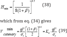
Where β≡σt + σcis the ratio of the characteristic tensile to compressive strength. Figure 9b shows the L≡l/h1 resulting in the minimum material volumes for variations of β, and Figure 9c
plots the corresponding minimum volumes. Taking as an example the
characteristic tensile and compressive strengths to be equal, β =
1 it can be seen that the total volume of primary structural material
for the catenary-type bridge, having foundations capable of reacting the
horizontal cable force, is kv = 1.0 compared with the value of kv
=14 when the horizontal thrust is resisted by a compressive force over
the length of the deck as summarized in eq. (14). It is also noteworthy
that this reduced value of material volume for the catenary-type bridge
is the same as the kv =1.0 for the harp-type cable-stay given by eq. (21), and just 30% greater than the kv =0.786 needed for the Mitchell optimum when β =
1 . However, it must be remembered that this super-structural material
volume for the catenary-type suspension bridge does not include
consideration of the cost of providing the foundation horizontal thrust
capacity. For a small number of spans this foundation costs averaged out
would nullify the equality in the provision of super-structural
material as compared with the harp-type cable-stay. However, the added
foundation cost will represent a diminishing span averaged cost when the
bridge has multiple spans. These issues will be considered later in
relation to a discussion of optimization based upon cost rather than as
at present the material volumes.
Eq. (37) also makes clear that the choice of say l/h ≈20
chosen for the "blade of light" that comprises the millennium bridge in
London, will require 2.6 times the volume of primary structural steel
as that for the above minimum material volume, not to mention the 5-fold
increases in the horizontal thrusts required to be generated at the end
abutments.
Harp-Type Cable-Stay Bridg E Foundation Thrust
Consider again the multi-span harp-type cable-stay bridge of Figure 3a but constructed in such a way as to require the same horizontal thrust at the end foundations as the catenary-type bridge of Figure 9a. This situation is summarized in Figure 10a with the changes to the deck axial force shown in Figure 10b. Over a typical span l the compressive force will vary linearly from a maximum tension of  to a maximum compression of
  . Hence the total product of compression forces integrated over their
lengths consists of two contributions - the pylon and the reduced value
from the deck - and is given by
. Hence the total product of compression forces integrated over their
lengths consists of two contributions - the pylon and the reduced value
from the deck - and is given by
to a maximum compression of
. Hence the total product of compression forces integrated over their
lengths consists of two contributions - the pylon and the reduced value
from the deck - and is given by 
with the Maxwell constant again On the basis of
eq. (9) the sum of the product of the tension forces times their lengths is in this case
On the basis of
eq. (9) the sum of the product of the tension forces times their lengths is in this case
On the basis of
eq. (9) the sum of the product of the tension forces times their lengths is in this case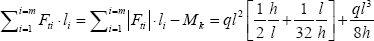
Notice again that through the use of the Maxwell
lemma it is not here necessary to calculate separately the volumes of
the tension members, as was done in Ref. [1]. It follows that the total material volume will be given by
of the material strength parameter  For typical ratios of the high strength steels used for the tension
cables and the lower grade steels used for the compression members, the
least material volume will occur for values of β in the range 1 to 3, for which the optimal
For typical ratios of the high strength steels used for the tension
cables and the lower grade steels used for the compression members, the
least material volume will occur for values of β in the range 1 to 3, for which the optimal  would be in the range 2.3 to 2.8; this contrasts with the least volume solution of
  when the full horizontal thrust is resisted by the deck.
For typical ratios of the high strength steels used for the tension
cables and the lower grade steels used for the compression members, the
least material volume will occur for values of β in the range 1 to 3, for which the optimal would be in the range 2.3 to 2.8; this contrasts with the least volume solution of when the full horizontal thrust is resisted by the deck.
Reductions in optimal material volumes for the harp-type cable-stay when the horizontal thrust of  are taken by end support reactions as compared with those for which the
thrust is resisted fully through deck compression can be seen in Figure 10c to be considerable, but far less extreme than those for the catenary type bridge shown in Figure 9c. Given that the cost of providing foundations capable of resisting the horizontal thrusts of
are taken by end support reactions as compared with those for which the
thrust is resisted fully through deck compression can be seen in Figure 10c to be considerable, but far less extreme than those for the catenary type bridge shown in Figure 9c. Given that the cost of providing foundations capable of resisting the horizontal thrusts of  will be the same for both the systems of Figure 9c &10c, it can be seen that for values of
  the optimal harp-type cable-stay requires less super-structural steel
than that required for the optimal catenary-type. However, for
the optimal harp-type cable-stay requires less super-structural steel
than that required for the optimal catenary-type. However, for  the situation is reversed and the catenary-type bridge would likely be more materially efficient.
are taken by end support reactions as compared with those for which the
thrust is resisted fully through deck compression can be seen in Figure 10c to be considerable, but far less extreme than those for the catenary type bridge shown in Figure 9c. Given that the cost of providing foundations capable of resisting the horizontal thrusts of will be the same for both the systems of Figure 9c &10c, it can be seen that for values of
the optimal harp-type cable-stay requires less super-structural steel
than that required for the optimal catenary-type. However, for the situation is reversed and the catenary-type bridge would likely be more materially efficient.
While it may be feasible to construct cable-stay
bridges for which the horizontal components of cable tension due to dead
load are resisted by a combination of deck tension and compression this
could not be possible for the subsequent application of live loading.
To achieve this situation for the dead loading would require a deck
connection similar to a typical expansion joint for which no horizontal
force could be transmitted. This form of construction joint would be
inconsistent with the needs of flexural continuity required to resist
loads that have an anti- symmetrical component applied to adjacent
spans. For this reason the situation discussed in Figure 10 must be considered impractical for the components of live loading.
Some Further Practical Considerations
The above analyses ignore many factors likely to
influence the design of suspension bridges. First, it assumes that the
material volumes required for what one might regard as secondary
structural action will be little influenced by the changes in the
structural material volumes needed to carry the primary loads. These
secondary structural actions would include the structural members
required to transmit the local deck loads back to the locations where
cables pick-up the reactions. And they would include bracing members
required to limit the effective buckling lengths of compression members
in the deck and pylons. So long as the cable spacing and forms of
bracing are held fairly constant over the various designs these
secondary structural components could be anticipated to require
comparable amounts of secondary steel. For this reason the above
limitation to consider just the volumes of primary structural components
should provide realistic comparisons of relative efficiency.
However, the levels of the overall bending in the
stiffening decks will depend upon the relative stiffness of the deck and
the cable support systems which will in turn be very dependent upon the
various design parameters. This would impact upon the material
requirements for the stiffening girder that could have a secondary
influence upon the total volumes of structural material required.
Secondly, while dead load would conform to the assumed restriction of
equal uniformly distributed loads over adjacent spans this may not be
the case for live loading. Unequal live load distributions on adjacent
spans will induce considerable bending moments in both the decks and
possibly pylons. However, it can be shown that the purely anti-symmetric
components of loading will induce roughly equal bending moments in the
spans of all the bridge forms considered, requiring similar volumes of
material required to provide these bending moment distributions. This
would have the effect of making the determination of the optimal designs
relatively insensitive to the non-uniform distributions of live load.
Thirdly, and related to this, the dynamic response to wind and
earthquake loadings have not been considered. These too could impact
upon the stiffness required of the deck and therefore on the amounts of
material needed for the deck. Fourthly, as the spans increase some of
the individual components will require additional structural material
just to support their own weight. For example the stay cables will
increase in length in direct proportion to the increasing span. Rather
than being able to carry the primary loads by direct tension the
catenary action within each separate cable will require additional
structural material to carry the additional tension and bending caused
by the cable weights. This is likely to be more important for most of
the cable-stay bridges than for catenary-type bridge since for the
latter most of the components will have their characteristic lengths
kept relatively constant as the spans increase. For example, the
distances between vertical hangers will not generally be increased in
direct proportion with the increasing span, so that local bending in the
deck or the local self-support of the cable will not be a major fact in
determining the sizes of members required. For this reason most of the
feedback effects for the self-weights of components can simply be
incorporated in an adjustment to the dead load component of the
distributed load .
In assessing the impacts on required material volumes
arising from different characteristic strengths of materials in tension
and compression no allowance has been made for the use of different
grades of material for different components. For example, it is likely
that considerably higher grade steels would be adopted for the tension
cables than those used for the deck. So where there is tensile action
occurring in the deck it is likely that the volumes of steel required
would be underestimated compared with those required had a lower grade
steel been assumed. To keep the presentation simple, as is consistent
with the approach being adopted, this has not been considered in the
above presentation. However, it would be a relatively straight forward
adjustment to the calculations presented to include these effects. In
any case a potentially even more important factor that has seemingly
been neglected is to base the considerations of which structures provide
the most efficient choice purely on material volumes - or equivalently
weight given that most steels have roughly the same density. The costs
of materials, their fabrication and erection are likely to be highly
dependent upon the grades of steel adopted and the nature of the
components and especially the connections for which these materials are
being used. The unit cost of fabricating and erecting the high strength
steels used for the tension cables is likely to be considerably greater
than the material, fabricating and erection costs for mild steel used
for the compression members, whose dimensions are likely to be more
critically controlled by buckling. Because buckling capacities will be
much more dependent upon the elastic modulus and because the modulus of
elasticity for high grade and low grade steels are broadly the same,
there is likely to be much less advantage for compression components in
adopting the high strength steels.
A simple way of modifying the above discussion of
relative efficiencies based upon material volumes to the consideration
of cost optimization is to consider that the cost of tension components
is say ct per unit volume (or weight) and that for compression
components the unit cost is cc. This means that replacing the parameter  with .the alternative compound material and cost parameter
  will allow all the expressions derived above to be adjusted to cover
the combined consideration of differences between the strengths in
tension and compression as well as the differences in cost of the
different grades of steel and their fabrication as expressed by whether
they are in tension or compression. Bringing all of the above
calculations together the results could be summarised in the following Figure 11. For each of the different classes of structure the total costs C minimized with respect to each of the parameters considered above are expressed in the form
will allow all the expressions derived above to be adjusted to cover
the combined consideration of differences between the strengths in
tension and compression as well as the differences in cost of the
different grades of steel and their fabrication as expressed by whether
they are in tension or compression. Bringing all of the above
calculations together the results could be summarised in the following Figure 11. For each of the different classes of structure the total costs C minimized with respect to each of the parameters considered above are expressed in the form
with .the alternative compound material and cost parameter
will allow all the expressions derived above to be adjusted to cover
the combined consideration of differences between the strengths in
tension and compression as well as the differences in cost of the
different grades of steel and their fabrication as expressed by whether
they are in tension or compression. Bringing all of the above
calculations together the results could be summarised in the following Figure 11. For each of the different classes of structure the total costs C minimized with respect to each of the parameters considered above are expressed in the form

In terms of the material and cost parameter is  .
Again, fabrication costs do not just depend upon the grade of steel but
also on the type of fabrication and erection involved. For example the
cost of on-site fabrication and erecting of a high compression strength
steel pylon might be considerably different to the costs of erecting a
pre-fabricated deck from the same material. Again, if nuances are
required it would be possible to incorporate these within a modified
form of the above calculations.
.
Again, fabrication costs do not just depend upon the grade of steel but
also on the type of fabrication and erection involved. For example the
cost of on-site fabrication and erecting of a high compression strength
steel pylon might be considerably different to the costs of erecting a
pre-fabricated deck from the same material. Again, if nuances are
required it would be possible to incorporate these within a modified
form of the above calculations.Conclusion
One of the aims of this paper has been to provide
sufficiently simple analyses of structural behaviour to allow estimates
of material volumes or costs to help make rational decisions between the
relative merits of different structural forms. Although confined to
restricted classes of structure used for long span bridges, the
methodology described could equally be applied to other classes of
structural system. There are a number of issues that stand out from this
analysis. These will be drawn together with the aid of Figure 11
which shows, for each of the classes of bridge form considered, the
material volumes and cost estimates for providing the super-structural
steel as functions of the compound material and cost parameter,B .
Compound parameter B encapsulates an allowance for the different
material characteristic strengths in tension and compression, and the
different material, fabrication and erection costs for the elements in
tension compared with those in compression. There are a number of
potentially important conclusions that have emerged:
As would be expected, there is considerable advantage
in reducing the required super-structural material volumes by including
end foundations capable of resisting all or part of the horizontal
force otherwise resisted by the deck. For the catenary-type suspension
bridge having low values of the material strength and cost parameter B,
there is around 40% saving in material volumes for each span when the
horizontal component of the main cable is absorbed by the end support
foundations. The savings become even greater for higher values of B.
Whether for bridges having a small number of spans the additional cost
of providing the horizontal capability in the foundations would be
offset by the savings in super-structural weight would require separate
costing of foundation provision and superstructure. But what is certain
is that as the number of spans increase it is likely that the added
foundation costs would be more than compensated by the considerable
savings in super- structural costs.
While it is not the usual practice to do so there
would be similar savings to super-structure cost for cable-stay bridges
were they to incorporate horizontal load capacity in the end foundations
equivalent to those usually provided for the catenary-type bridge. This
is especially true for higher values of the material strength and cost
parameter B . However, to enable a multi-span cable-stay
bridge to resist live load components that display anti-symmetry with
respect to adjacent spans this strategy would be possible for just the
dead load contributions to the deck loading.
With the same foundation requirements in terms of
both vertical and horizontal load capacity, the harp cable-stay is
marginally more efficient than the catenary-type bridge for values of B < 3 , while the reverse is true forB >
3 . Hence the use of very high strength steel for the cables is likely
to favour the adoption of the catenary-type bridge as compared with
either the harp or the fan cable-stay bridges; although this advantage
is likely to be reduced when cost optimization is considered.
For the situation where the end supports are not able
to provide horizontal force capacity, both the fan and harp cable- stay
bridges provide considerably more efficient structures than the
catenary-type bridge over the entire range of material and cost
parameter B. In all cases the harp system is marginally more efficient than that of the fan configuration.
The use of radially directed multi-pylons at each
support provides considerably more efficient cable-stay bridge solutions
than any of the alternative cable-stay systems. When optimized in terms
of inclination angle even 3 radial pylons at each support result in
total material volumes very close to theoretical minimum volume provided
by the somewhat impractical Mitchell-type truss.
The optimal multi-pylon supports systems for low values of B <
2 require less super-structural material volume than either the
catenary-type or harp cable-stay bridges for which end supports provide
horizontal capacity. Even for higher values of B < 2 the
multi-pylon solutions offer very competitive super-structural weights
without the need for the provision of horizontal capacity at the end
support foundations. This suggests that for future economic design
serious consideration be given to the use of multi-pylon supports to the
cable nets.
Use of Maxwell's lemma is shown to provide an
efficient shortcut to the calculation of required material volumes. In
cases where the Maxwell constant is zero the total volumes of tension
and compression members are inversely proportional to their respective
characteristic strengths.
For very long span bridges it is likely that the
added material required for the individual members, responsible for
providing the primary load paths, to support themselves will be more
keenly felt for the various cable-stay solutions. In these circumstances
the catenary-type bridge will likely provide the most effective
solutions provided end supports are capable of resisting the inevitably
high horizontal thrusts.
Final Remarks
Over the past few decades it has become a matter of
concern that the conceptual design of even bridge structures has
decreasingly been undertaken by engineers. The reasons for this are many
but one factor that has contributed is suggested to be the dominance of
analysis in engineering education and over the past 50 years or so and
the overwhelming emphasis on analyses directed towards the development
and use of computer algorithms. While it is questionable whether the
more traditionally taught hand calculation methods did a lot more to
enhance physical and intuitive understanding of structural behaviour, so
vital for effective design, it has always seemed to the writer that we
have not exploited sufficiently the fact that analysis can now be so
effectively performed with readily available software. This could have
liberated those involved in engineering education to spend more time on
the fundamentals of structural behaviour as well as providing simple but
reliable methods of analysis which being more directly founded in
physics would develop the intuitive skills so vital to creative design.
It would have reduced the worrying trend that when faced with a novel
problem the response from too many engineers is not to sit down and
think about how this could be understood and approximated using simple
conceptual models, like those discussed here, but instead to consider
how the problem might be interfaced with whatever brand of software
happens to be available within the office. Little wonder that others are
too often in the driving seat of structural creativity.
Traditionally, bridges were perhaps the purest
expression of structural rationality in which the basic principles of
mechanics directed the engineer to the most appropriate form for a given
situation and choice of structural material. Over time our perceptions
of what looked right and consequently pleasing to the eye were most
likely what was right for the particular situation - just as in natural
structures formed through eons of evolutionary optimization what is
right becomes accepted as looking right. This theme has recently been
developed in Ref. [7]
where a detailed analysis of the Alamillo bridge in Seville showed this
to be a classic example of structures being used as a piece of art
rather than the art being a consequence of the structure representing a
true expression of the best use of material based upon the application
of sound and rational principles of mechanics. Now it seems this process
has been hijacked with many bridge forms having a closer affinity to
sculpture than with rational engineering. It is hoped that this theme
will be taken up in subsequent publications.
Perhaps if we are to reverse this trend it will be
even more important that future engineers spend more time developing an
ability to undertake simple scoping calculations. Only through a sound
understanding of how structures work and an ability to translate this
into simple models to allow the flow of forces through our structures to
be understood will it be possible for engineers to recover the
conceptual lost ground. In an age when waste and its contribution to
global warming are high on the agenda it is likely that clients will
require their structures to be part of the solution rather than part of
the problem. To this end it is to be hoped that the simple models, like
those outlined in this paper, will find an increasing role in
engineering education and professional design.
For More Open Access Journals Please Click on: Juniper Publishers
Fore More Articles Please Visit: Civil Engineering Research Journal
Fore More Articles Please Visit: Civil Engineering Research Journal


Comments
Post a Comment