Numerical Analysis of Stressed State of an Elastic Strip Plate with Collinear Cracks and Thin-Walled Inclusions at Antiplane Shear Loading- Juniper Publishers
Juniper Publishers- Journal of Civil Engineering

Abstract
In this paper, a long elastic strip plate with
collinear cracks at antiplane deformation in the case that each crack
tips are joined by thin- walled inclusions deformed according to the
known Winkler's model is considered. The uniformly distributed shear
forces causing the antiplane deformation of the plate are acting on the
horizontal sides of the strip and the edges of cracks are free of
inclusions. For convenience in numerical calculation the strip plate is
divided to several plates so that each segment has one crack at the
center. The solution of the stated problem via Fourier sine
transformation is reduced to singular integral equation (SIE), and,
consequently, to a system of linear equations. Numerical calculations
based on the Gauss Quadratic solution are achieved. For the main
characteristics of stated problem, such as the SIF, the crack opening,
the shear stresses on the edges of the inclusion, and the shear stresses
out-of-crack the obvious equations are obtained and the special cases
considered.
Keywords: Numerical analysis; S.I.F; Tip inclusions; Anti-plane Shear; SIE
Introduction
In this paper, we calculate the stress distribution
state and S.I.F of the crack tips and dislocations of edges of a long
strip elastic rectangular plate (Figure 1).
The stress Intensity is essentially decreasing the known strength and
durability of structural members and engineering parts. For this reason,
the necessity of theoretical investigation of stress concentration
zones and the development of the methods which decrease the stress
intensities is occurred. One of these methods was proposed in [1],
the edges of linear finite crack of elastic infinite plate at the end
areas are joined via thin-walled inclusion in the shape of continuously
distributed linear and nonlinear deformed springs, meanwhile, the plate
is subjected by uniformly distributed tensile remote stress
perpendicular to the central line of crack. Taking into account the
above-mentioned physical model of inclusions and based on assumptions in
[24],
the valuable decrease of stress intensity factors (SIF) at the end
points of crack can be achieved by the appropriate selection of elastic
and geometric characteristics of problem, and this can prevent the crack
propagation. Applying Fourier finite sine transformation, the solution
of stated problem can be reduced to the solution of singular integral
equation (SIE), and, consequently, via the known method [5-7],
the solution of singular integral equations can be reduced to the
system of linear equations. For the main characteristics of stated
problem, such as the SIF, the crack opening, the shear stresses on the
edges of the inclusion, and the shear stresses out-of-crack on the line
of its location, the obvious equations are obtained, the special cases
are considered and for various materials the decreasing trend of S.I.F
based on the various shear modulus were shown.

Governing Equation of Boundary Value Problem
Following the approach represented in [1] consider a prismatic elastic body with a rectangular cross-section in Cartesian coordinates Oxyz occupying an area Ω = {-∞≤x≤∞; -h ≤ y ≤ h; -∞< z <∞} and possessing a shear modulus G . The prismatic elastic body is rigidly clamped by the vertical edge x = -∞ and x = +∞ , and loaded by the shear forces equal to T (x) acting both in positive and in negative directions of Oz -axis at the horizontal y = ±h . Furthermore, on the symmetry plane y = 0 , the body Ω has several through-in-thickness cracks each in a shape of strip with length 2a on plane y = o and -∞< z <∞ at distances equal to 𝓁 (α < 𝓁/2). The shear forces of equal intensities T0 (x) are acting in opposite directions of Oz-axis on the upper (+) and lower (-) areas of edges ω±={y = ±0; 𝓁/2-b < xi < 𝓁/2 + b; -∞< z <∞ } (b <a) of the crack. Besides that at the ending areas

The edges of the crack are joined by the thin-walled inclusions with the shear modulus G
deforming by the Winkler model. Let's assume that the prismatic body Ω
subjected to the above-mentioned shear forces is in a state of anti
plane deformation in the direction of Oz-axis on the basic plane Oxy . The main rectangle D1 = {-∞≤ x ≤+∞; - h ≤ y ≤ h} with several cracks ω ={y = 0; 𝓁/2 - α < xi < 𝓁/ 2 + α} (0 < α<𝓁/ 2) is cross-section of the body Ω with the plane located on this plane Oxy (Figure 1).
It is necessary to determine the dislocation density
on the crack edges, SIF, the crack edges opening, the shear contact
stresses on the edges of the inclusion, and the shear stresses outside
the crack on the line of its location. For convenience in numerical
calculation the strip plate is divided to several plates so that each
segment has one crack at the center (Figure 2).

Now, let's derive the governing equations of the
stated problem. For this purpose, it must be initially mentioned that
the component uz = w (x, y) in the
direction Ox-axis is the only non- zero component of displacement in the
case of antiplane deformation, and harmonic function in the area D ω0. The components of shear stress τxz and τyz
are the only nonzero components of stresses. Therefore, the problem can
be mathematically stated as a boundary value problem in the following
way:
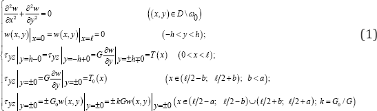
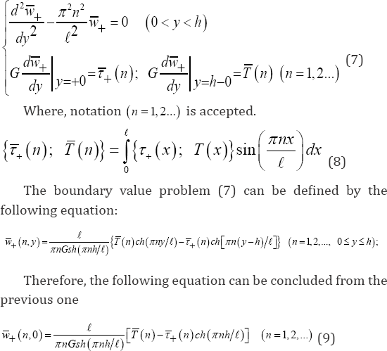
For of the determination of boundary value problem (1), the rectangle D is divided by Ox-axis onto upper D+={0 ≤ x ≤ 𝓁; 0 ≤ y ≤ h} and lower D-={0 ≤ x ≤ 𝓁; - h ≤ y ≤ 0} rectangles. The following supporting boundary value problems are considered for them.
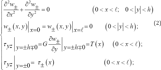
Where, the sign "+" and "-" are related to the rectangles D+ and D- , correspondingly.
τ( x) is the unknown fracture shear stress outside the crack ωa on the its line.
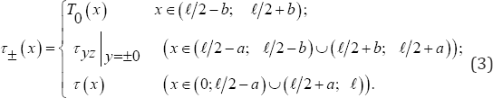
Taking into account the symmetry of stated problem with respect to -axis
ω+ (x, y) = -w_ (x, y) (0 < x < 𝓁); τ+ (x) = τ_ (x) (0 < x < 𝓁); (4)
Consequently, the determination of supporting problem (2) for the rectangle D+ can be considered only. Based on the reference [8], the above-mentioned problem can be determined via Fourier finite sine transformation on the variable x .
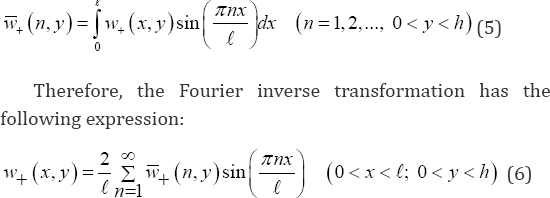
Multiplying by sin(xnx/𝓁) both sides of the differential equation and the border conditions of (2), and integrating it from 0 to 𝓁 , Fourier finite transformation (5) can be applied to the boundary value problem (2) for D+ . The boundary value problem in Fourier transformations can be obtained after the simple reductions.
The Singular Integral Equation
After some simple transformations and calculations according to [1] and [9-11] the following equations can be derived:
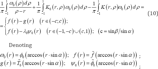
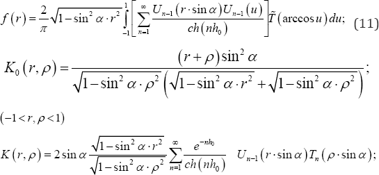
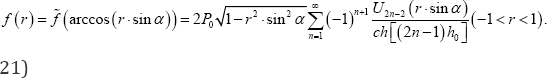
The first integral of equation (10) for ρ=r is assumed as a main value of the Cauchy�fs relations. Meanwhile, Tn(x) and Un-1(x) are Chebyshev polynomials of the first and the second kind,
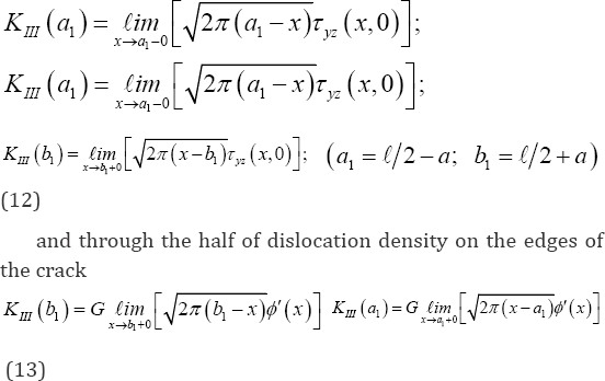
Finally, the stress intensity factors at the end points (a1;b1) of the crack can be expressed by the following equations:
Gauss Quadrature Method
Now, as it was mentioned above, the determinative
singular integral equations (S.I.E) (10) can be reduced to a system of
linear equations and following to the approach represented in [1], the determinative S.I.E (10) can be reduced to the system of Algebraic linear equations as follows:
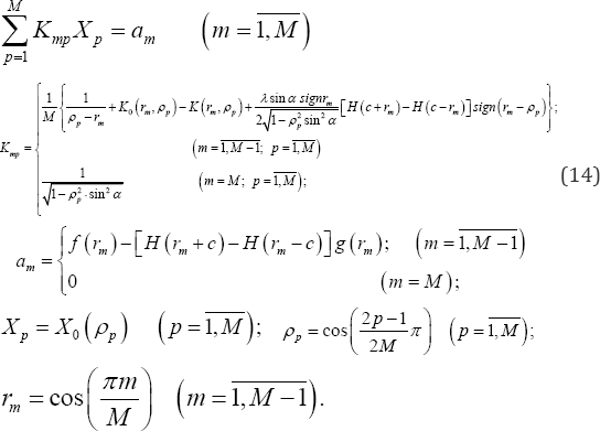
Where M is an arbitrary natural number, rm and ρp are the roots of Chebyshev's polynomials of the first kind Tm (ρ) and the second kind UM-1 (r)
The main physical characteristics of the stated
problemcan be expressed by the determination of the system of linear
equations (14). The plate shear stress out of the crack at the interval
y=0 ,x ∈ (0,𝓁 /2-α)∪(𝓁/2 + α,𝓁) can be obtained as below:
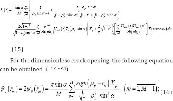
For the dimensionless shear stresses on the edges of
inclusion applying equation (20), the following equation can be derived
Where,X0(1) the value is applied through the Lagrange interpolation coefficients based on Chebyshev's polynomials.
Therefore, solving of the system of linear equations (14), the
main physical characteristics of the stated problem can be expressed by equations (15)-(18).
Numerical Calculation
For numerical calculations we consider a special case
of the loading of the rectangular plate. For this case, the crack edges
are free of shear forces, and shear concentrated force acting on the
horizontal sides of rectangular plate:
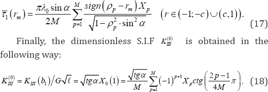
T0 (x)≡ 0, T (x) = Pδ(x - 𝓁/2),
Where, δ(x) is a certain Dirac Delta function. In
this case g(r)≡0, in (11), as well as, with respect to equation (8), the
following equation has been obtained
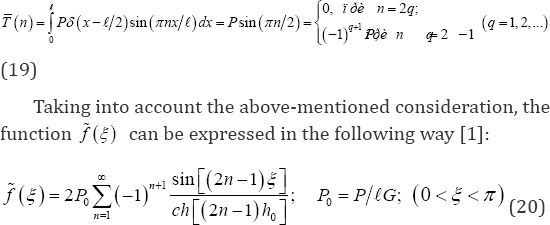
And the function f(r) from equation (11) can be obtained in the following way

It is obvious that the function ω0 (r) with respect to the symmetry of line x = 𝓁/ 2 in this special case, and, consequently, the function x0 (r)
according from equation (14) are odd functions, therefore, the
components of the second integrals in equations (10) and (15) containing
polynomials r or t in arguments tend to zero, so that, the above-mentioned equations and the kernel-matrix Kmp of system of equation (14) are simplified .and the expressions of functions  and f (r) are from equations (20)-(21). The numerical analysis of the main characteristics of stated problem can be carried out for
the considered special case. Antiplaine shear stresses τ0 (t) on the edges of inclusions and out of crack based on the various shear modulus GO were calculated and shown in (Figure 3) also
decreasing dislocation of crack edges due to inclusions tip repair are shown in (Figure 4).
and f (r) are from equations (20)-(21). The numerical analysis of the main characteristics of stated problem can be carried out for
the considered special case. Antiplaine shear stresses τ0 (t) on the edges of inclusions and out of crack based on the various shear modulus GO were calculated and shown in (Figure 3) also
decreasing dislocation of crack edges due to inclusions tip repair are shown in (Figure 4). 
Conclusion
Numerical calculations show that the repair of crack
tips causes avoiding the singularities and reduces the anti-plane S.I.F
KIII , about 50 percent, also for strengthen and stop the crack
propagation near to region at the tips, it is not need to use a material with very high shear rigidity value G0 [12].
Meanwhile the crack opening C.O.D decreases about 50 percent, and in
addition the shear stresses at the crack tips fall down near to 30
percent.
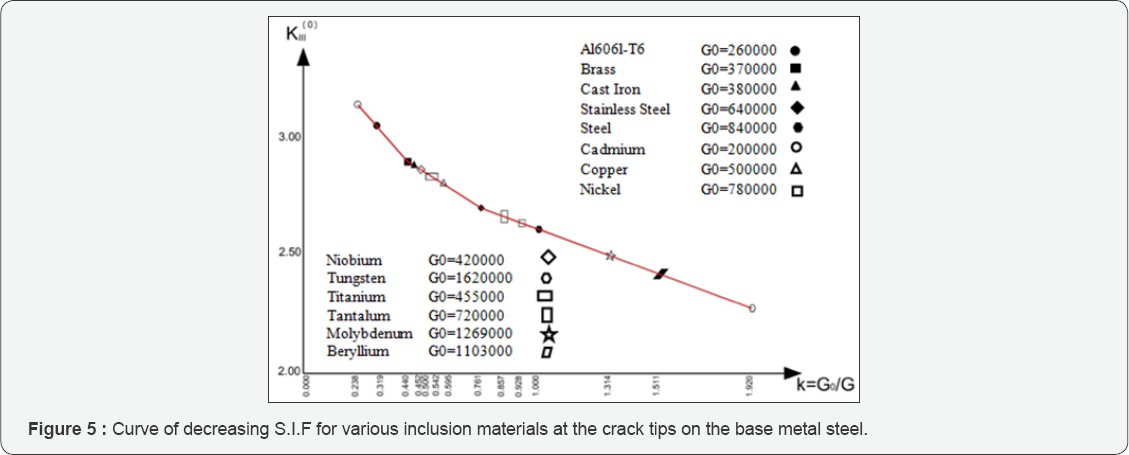
The linear Algebraic system of equation (14) were
solved regarding to relations (19)-(21) for the special case of
anti-plane shear loading for several metals on a base metal steel for
the main plate [13]. The shear moduli of the metals over the steel shear modulus are represented as a ratio on the horizontal axis in (Figure 5).
The stress intensity factors S.I.F K III that are
very important and show the intensity or index of upper limit of shear
stresses magnitude calculated through the equation (18) that are shown
in (Figure 5),
which presents the decreasing trend of S.I.F curve when the ratio of
k=G0/G goes up. It also shows that the crack tip repairing by adding
another material at the tips to prevent crack propagation, can reduce
the S.I.F about 50 percent, means this approach is very effective to
avoid the crack propagations in cracked plates, mathematically is a
treatment for well-known singularities at the crack tips, defects and
holes.
For More Open Access Journals Please Click on: Juniper Publishers
Fore More Articles Please Visit: Civil Engineering Research Journal
Fore More Articles Please Visit: Civil Engineering Research Journal


Comments
Post a Comment