Experimental Evaluation of Gravel Bed Up-Flow Roughing Filter for Pre-Treatment of Rural Community Water Treatment- Juniper Publishers
Juniper Publishers- Journal of Civil Engineering
Abstract
Water is essential for life. This study evaluates
gravel bed up-flow roughing filter (URF) for pre-treatment of rural
community water treatment. The pilot unit consisting of acrylic pipe
with internal diameter 90mm was used for study. This column is
vertically fixed, having an inlet at bottom so that filter can be run
for up flow mode of operation. For sake of roughing filtration,
artificial raw water was continuously passed through laboratory column
packed with quartz gravel media. Media size range was 16mm-2.36mm. The
media was filled in the column in three layers. Filter was studied for
the flow rates in the range of 5-20m/hr. The results investigated shows
that turbidity removal by gravel bed roughing filter is very good it is
almost 85% - 90%. By and large, based on the present experience of the
different filtration experiments it can be certainly inferred that the
URF is a dependable alternative for conventional pretreatment of water
in rural community water treatment.
Keywords: URF; Rouging filter; Water treatment; Gravel media
Introduction
The development of human settlements cannot be
assured without securing and maintaining an adequate supply of water.
Naturally availed water can contain a wide range of ingredients that can
make people awkwardly ill or make it unsuitable for certain
applications. So, ensuring appropriateness of water in view of a
proposed use is an inevitable task. The necessity of water purification
was understood by man at the very outset of civilization. Wholesome
water is one which is safe, potable, and contains essential nourishing
minerals in adequate quantity. So the quest for progressively better
water continues.
However, an increase in manmade water pollution, the
development of technical and public health science, as well as the
consumer’s greater need for clean water contributed to the development
of the water purification technology [1].
Water, as required for the life, is rarely available
in the natural world. Therefore, wide arrays of treatment procedures are
evolved to cope up with different quantities, initial qualities, and
finishing requirements of water to be treated. In the present day, the
main objective of water treatment facilities in India is to produce safe
and potable water. With ongoing development of the country it will be
obligatory to address the issues related with safe, potable and
wholesomeness of water to be supplied and sustainability of treatment
procedures to be followed.
Contemporary water treatment technology is the
outcome of vigorous and systematic efforts of scientists and
technologists, working for more than last hundred and fifty years.
Surface water assumed the status of prime source of water as it is more
suitable for the use, and easier to treat in comparison with water from
other sources such as ground water or sea water. So, from the 1850s to
about the 1950s, water treatment facilities were frequently designed by
experienced engineers using empirical rules and succeeded design
practices. However, after the 1950s, a greater understanding of
fundamental principles underlying treatment processes was required to
deal with complexities due to growing demand for water, and increased
pollution of water bodies.
Pretreatment comprising of coagulation, flocculation
and sedimentation is known to be essential for rapid sand filtration. It
is because pretreatment not only trims down the particles but reduces
the surface charges of micro flocs to be removed by final filters.
However, the conventional pretreatment is costlier in view of large
capital as well as operation costs. Therefore, there
is a need for alternative pretreatment methodology to replace
conventional pretreatment units. Roughing filtration (RF) are low-cost
primary treatment options that could potentially improve the water
quality. The goal is that the primary treatment reduces the turbidity to
be within the 5-10 NTU range or lower so that RSF can be effective.
A roughing filter can effectively remove
colloidal-size particulates without the addition of coagulant chemicals
and also provide a large solids storage capacity at low head loss.
Sedimentation and adhesion to media particles are the main particle
removal mechanisms [2].
So, Roughing Filtration could be considered as dependable technique for
pretreatment. Subsequent to study of many water treatment plants in
India, CPCB [3]
reported rather inadequate pretreatment at many plants. It is reported
that chemical feeding is unsatisfactory, flash-mixers are defunct and
settling basins are overloaded. The use of roughing filtration would
obviate need of flash mixers and settling basins.
Depending on the rate of filtration, filters can be
classified as slow sand filters, rapid filters, or high rate filters.
Due to common availability, sand and gravel are the most common granular
media. Mono-medium, dual media and multimedia filters are also
developed to enrich the filtration process. Direction of flow during
filtration process results in different types of filters as down flow,
up flow, horizontal flow, radial flow and bi-flow filters. Filters
utilized in water treatment are also classified as gravity or pressure
filters based on driving force. Pre-filters or roughing filters
primarily aim at removal of impurities basically larger in size and
provide pretreatment to reduce the load on final polishing filters.
Significant aspects, design and operational parameters of the commonly
used of filters and roughing filters are provided in Table 1.

Conventional Water Treatment Units

In reference [4,5]
the primary purpose in surface-water treatment is chemical
clarification by coagulation and mixing, flocculation, sedimentation,
and filtration. These unit processes along with disinfection work to
remove particles, naturally occurring organic matter (bacteria, algae,
zooplankton, and organic compounds), and microbes from water to produce
quality water that is noncorrosive. Specifically, coagulation and
flocculation work to destabilize particles and agglomerate dissolved and
particulate matter. Sedimentation removes solids and provides virus
removal. Filtration removes solids and provides 1-log virus removal.
Finally, disinfection provides microbial inactivation and 2-log virus
removal Figure 1.
Simply stated, water primary treatment is any
physical, chemical, or mechanical process used before main water
treatment processes. It can include screening, pre sedimentation, and
chemical addition.
Non-Conventional Pretreatment Units
The electro coagulation floatation process consists
of electrolytic reactor with aluminum electrodes and a separation
floatation tank. The colloidal particles present in the water are
subjected to coagulation and flocculation by aluminum ions dissolved
from the electrodes. Hydrogen gas generated at cathode floats the flocs [6].
Performed experiments on laboratory setup and concluded that
electro-coagulation performed better than conventional coagulation with
aluminum sulphate for treating a model colored water, 20% more DOCS was
removed for the same Al dose.
Kardile [7]
has worked on a new unconventional treatment plant at Varangaon. The
system was designed for daily water supply of 4.20 MLD. He introduced
gravel bed flocculation unit of 3m*3m*2.5m in water treatment plant.
Gravel bed flocculation provides a promising solution to replace
mechanical flocculation unit for treatment of turbid water sources for
small capacity plants.
Bhole et al. [8]
have introduced "New concepts in low cost treatment plants". They
conducted experiments on pretreatment unit which combines principles of
tapered velocity gradient flocculation and solids contact flocculation.
Background on Roughing Filtration
Wegelin [1]
points out that roughing filtration is a process for separating
suspended impurities from water by passing through porous media.
Particle removal is one of the main objectives of filtration. Gravel
filtration has been used in water treatment since the early 1800s, when
it was first used in Scotland to pre-treat water prior to sand
filtration. Gravel filtration soon disappeared due to the advent of
chemical and mechanical water treatment. However, gravel filtration
reemerged in the 1970's and 1980's mainly in developing countries as
roughing filters, because those roughing filters do not require
sophisticated mechanical equipment or the use of chemicals.
Wegelin [1]
mentioned, roughing filtration technology is used as primary treatment
to polish the raw water quality for the improvement of performance of
slow sand filtration. But it may be used without slow sand filtration,
if raw water originates from well protected catchment area and having
minor bacteriological contamination. Therefore in rural water supply
systems roughing filtration becomes an appropriate technology.
So far theory of roughing filtration is not amply
established as the roughing filtration is not employed widely. It is
being considered as a remedial measure to reduce turbidity of water to
be applied to slow sand filters. Presently, the slow sand filtration is
almost abandoned in view of increased water demand and large area needed
for it. However, the roughing filtration could be employed for rain
water harvesting as well as an alternative for conventional
pretreatment. Ease of operation and maintenance in roughing filtration
makes it appealing for small capacity water treatment plants in rural
area.
As the pore sizes in roughing filter media are quite
larger than media in all other granular filters, head-loss developments
are smaller and the filter can run for more duration. So, the
regeneration is required less frequently. However, the regeneration of
roughing filter is rather distinct in comparison with other granular
filters. The larger media grains need too large flow rates for
fluidization. So, the cleaning by draining the bed is adopted at many
places. Smaller gravel in roughing filters could be cleaned by fluidized
washing. Suitable techniques could be appropriately combined to
regenerate roughing filter as and when required.
Materials and Methods
In pursuance of set objectives for the present work, laboratory experiments were planned and performed.
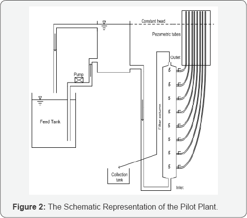
Figure 2 shows the schematic representation of the pilot plant unit and Figure 3 shows an actual picture of the filter unit.

Experimental setup
Filter column: The filter column used for
laboratory experiment is an acrylic pipe with internal diameter 90mm.
This column is vertically fixed, having an inlet at bottom so that
filter can be run for up flow mode of operation. For sake of roughing
filtration, artificial raw water was continuously passed through
laboratory column packed with gravel media.
In order simulate field conditions constant head tank
is provided. The artificial influent from feed tank is pumped to the
constant head tank. The overflow from the constant head tank is allowed
to pass into feed tank. So, the artificial clay suspension in feed tank
was in incessantly stirring condition due to pumping and recirculation
from constant head tank and there was almost
no settling in feeder tank.
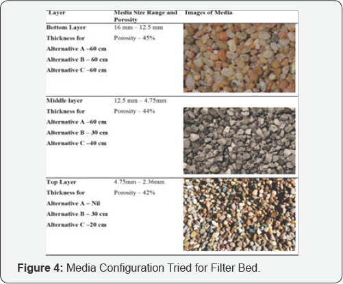
Filter media: Media used for filter bed is quartz gravel
Media size range was 16mm-2.36 mm. Stratification and configuration tried was as shown in Figure 4.
The media was filled in the column in three layers. Prior to packing
each layer in column, filter media was washed thoroughly with tap water.
Media was packed in the column in 5 cm increments and tamped down before
pouring additional media. After each layer of filter media a temporary
perforated plate was placed on and pressed tightly against the top of
the filter media.
Head loss and sampling ports: The filter
column has 8 sampling ports as well as 8 ports for determining head loss
at various depths of media. The inlet port is at bottom and first
sampling port is provided at a distance of 20cm from inlet port and
other successive ports are arranged accordingly. The seventh port is at
the top of the filter followed by output.
Flow control arrangements: A centrifugal (0.25
hp) pump is used to pump the influent water from the feeder tank to the
constant head tank. Constant head arrangement is provided by allowing
overflow from constant head tank. The overflow from constant head tank
is again directed to the feeder tank.
Flow rate arrangements: The filter was run at the constant flow rate. A flow control valve at the outlet of the column is used to control of flow rate.
Characteristics of water used: For the present
study, bore water and river bank clay was used to prepare artificial
influent. The bore well water was used for fluidized washing as well as
for Back-flushing the filter bed as and when required.
Suspension of river bank clay: For the
experimental study, artificial turbid water prepared in laboratory was
used. The turbidity was created by adding river bank clay to bore well
water. Prior to each experiment, the clay was hydrated in bore well
water overnight, dispersed in a blender, and mixed with additional water
to the desired initial turbidity.
Coagulation: Alum was used as coagulant. The
stock solution of alum was prepared in distilled water. It was added in
feeder tank in predetermined doses and mixed thoroughly every time while
preparing influent as desired for each set of filtration experiment. As
overflow water from constant head tank was recirculated into feeder
tank, there was continuous agitation and the possibility of settling of
particles in the tank was reduced. Further the stirring condition also
helped for better mixing of coagulant with raw water. The doses were
determined by conducting standard jar test.
Measurements of parameters
Turbidity measurements: Removal efficiencies
for all experiments were based on turbidity measurements (NTU). All
turbidity measurements were directly done, using a digital turbidity
meter of Hach make (2100P Portable Turbidimeter).
Flow rate: Flow rates were determined by
collecting effluent in calibrated jar and recording time required for
collecting 1 L of effluent in the jar. Flow rates were determined at the
predetermined time interval i.e. every one hour.
Head loss: The head loss measurements were
carried out and recorded at every hour and at all ports of filter
column. Piezometric tubes were used to measure head at each port.
Results and Discussion
Various filtration experiments were conducted in
order to acquire experience regarding performance of the roughing
filter. The observations made are put forth in this chapter along with
the discussions and significant findings.
Design of experimental set-up and operational parameters studied
Design of experimental set-up and operational
parameters are of immense importance in the study as they determine
rationality of findings based on the study. So, the design of
experimental set-up and operational parameters were carefully
considered.
Filter bed adopted: The configuration of
filter bed is the essence of all filtration processes. The
characteristics of filter media and depth of filter bed govern the
crucial parameters. The quartz gravel was used in the present study. In
line with the aim of pre treating the turbid water the coarser media
(2.36mm- 16mm) was selected unlike the finishing filters where effective
size of sand used is about 0.5 mm. As in the present study the URF was
challenged with coagulated and flocculated influent the largest gravel
size adopted was 16mm.
The stratified filter bed was adopted unlike the
finishing filters wherein un-stratified bed is deployed. For finishing
filters stratified bed are avoided in order to get rid of intermixing at
the media interfaces which can produce higher head losses. Further
highly fluidized washing of URF is to be never tried due to larger media
grains which require unworkably large fluidizing velocities. So, the
stratified bed was adopted with three different layers with gravel size
ranges as 2.36-4.75mm, 4.75-12.5mm and 12.5-16mm. The layer depths were
optimized to avail optimum removal performance as discussed in
subsequent sections. The total depth of 1.2 was adopted in the present
study.
Flow rates rtudied: The flow rates to be
deployed depend on target effluent, quality of influent, and more
crucially on economic feasibility. Good quality of target effluent and
poor quality of influent demand lower flow rates whereas greater
economic feasibility would demand higher flow rates. In this view the
flow rates in the 5-20m/hr were tried in the present study. Earlier
studies for roughing filtration are carried out even with flow rates of
1m/hr for pretreatment of water to be applied on slow sand filters
Wegelin [1].
Considering increased water demand, the aim to accomplish only
pretreatment, set target turbidities and more decisively economic
interests the flow rates adopted in the present study could be
proclaimed to be appropriate.
Optimizing filter bed configuration
For finding optimum media configuration, different
combinations of different sizes of gravel media were tried. The total
depth of media in URF column was 120 cm as aforesaid Wegelin, [1]. The different configuration of media as considered in alternatives A, B. and C were tried (Figure 4).
The filter runs were conducted with influent turbidity of 20-100NTU and
a coagulant dose of 5-40mg/L. Constant flow rate of 15±0.4m/ hr was
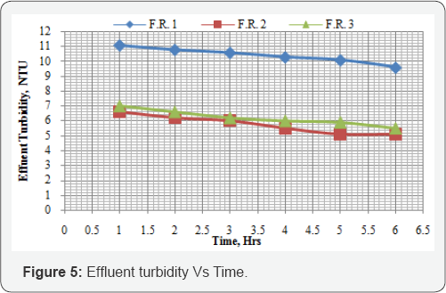
applied. It is desired to have effluent turbidity below 10 NTU.
Although effluent turbidities observed for the
alternative B, are superior to some extent for all filter runs, the
total head- losses for the alternative B are significantly larger. The
head losses after6 hr for the alternative B is 40-55% larger than for
the alternative C. So, the configuration - alternative C is considered
as the best configuration as the removal efficiency was as desired and
head- loss development was considerably less in comparison with the
configuration alternative B (Figure 5).
Clean bed head-losses
Clean bed head-losses, also known as initial
head-losses are amongst the significant hydraulic focuses that are
relevant to design of filtration systems. Depth-wise initial head-losses
are informative in respect of stratification of filter bed. Further,
initial head-losses influence the head available for actual filtration.
Initial head-losses across the filtration system are inclusive of losses
in the system without filter bed i.e. piping with accessories and
filter bottom with under-drains. Therefore they are also useful to
evaluate system components other than the filter bed.
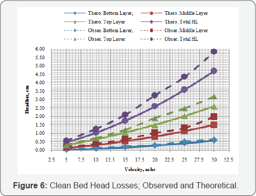
These losses are found to vary nonlinearly and are
directly proportional to flow rate. The clean bed head-losses for the
URF layers with larger media grains were lower than that for layers with
smaller media grains due to larger grain sizes and porosity of the UF
filter. Theoretical clean bed losses, calculated using Ergun's equation,
are compared with observed head losses.
The observed initial head-losses for different flow rates, at different depths of sand beds are plotted in Figure 6 the
depths considered are measured in the direction of the flow through
gravel media. The observed initial head-losses are marginally higher
than computed head-losses for all layers as apparent from Figure 6.
Ripening behavior of filter
This first stage of maturation of filter is known as
ripening. During the process of ripening the clean filter bed gets
conditioned due to attachment of particles from influent. The removal
efficiency of a filter continues to improve as the deposits build up in
media during ripening period.
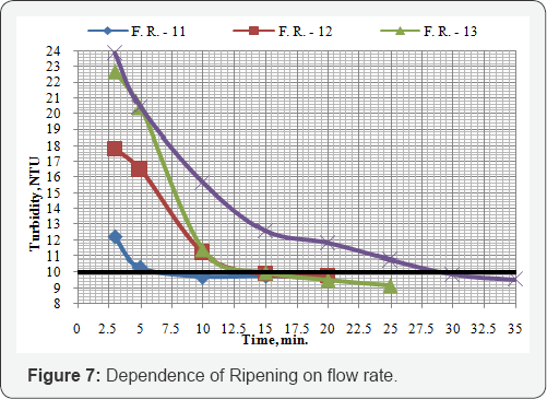
In general ripening periods observed for URF are
15min- 1hr. Similar to those for finishing filters (15min-2hr). Though
grain size in URF is large ripening periods are comparable with drinking
water standards [9] As seen from Figure 7
the ripening of URF is dependent on filtration rate which corroborates
with the earlier research on ripening of rapid sand filters, Cranston
and Amirtharajah [10].
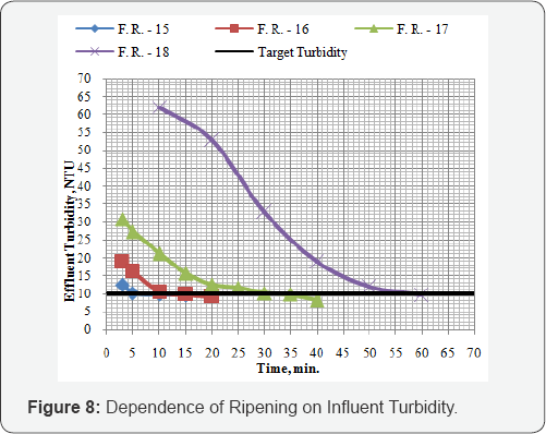
So, in order to deal with inadequate effluent during ripening period it
advisable to recirculate the inadequate effluent and to provide
multiple units of URF operating in staggered manner Figure 8.
Effect of flow rate on removal efficiency and head loss development
For determining optimum flow rate for URF, removal
efficiency and head loss development are crucial. Hence, the filter runs
on URF were carried out to study effect of flow rate on removal
efficiency and head loss development. URF was run for 6hrs. Flow rates
were varied from 520m/hr and different influent turbidities were tried
(25-100 NTU) with the respective coagulant doses. It was desired to have
effluent turbidity below 10 NTU.
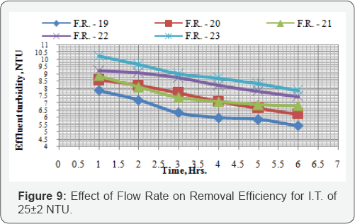
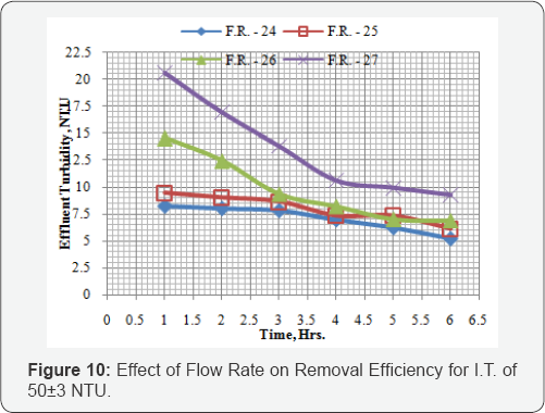
Observations for influent turbidity 25±2 NTU and 50±3 NTU are illustrated in Figure 9,10.
In general it is found that with increase in flow rates removal
efficiencies reduce and head losses increase. Since desired turbidity is
10 NTU and URF is found to take more than reasonable time for ripening
at higher flow rates. So, for higher turbidities the only option is to
run the URF at lower rate (5m/hr.). However such higher turbidities are
for very small period during the year. For the normal turbidity as seen
from the different runs discussed earlier, flow rate of 15m/ hr. is
found to be reasonable in order achieve desired removal performance.
With this flow rate, filter will generate more amount of effluent/sqm,
so that, overall cost of treatment will be more affordable.
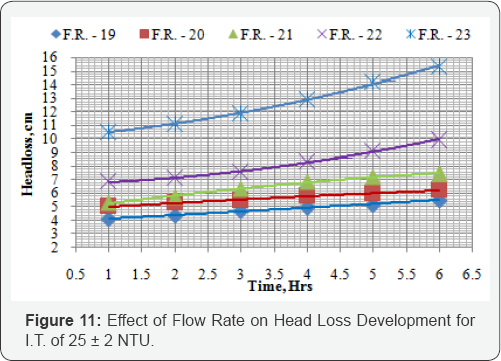
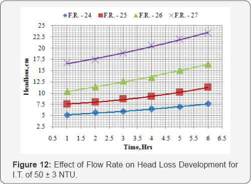
Observing Figure 11,12 it
can be seen that for smaller flow rates i.e. 5m/hr and 10m/hr head
losses are low enough whereas for higher flow rates, like 20m/hr and
above, head losses are too high. Keeping in mind head-loss development
too, constant flow rate of 15�0.4m/hr is recommendable for URF.
Performance evaluation of URF with optimal design and operating parameters
To evaluate performance of the URF unit, effluent
turbidities and head losses at different level and at different time
intervals are very expedient. Further, an experience of long duration
runs is essential for advocating the technique for field use. Keeping
this in mind the URF was run for longer duration and turbidity and
head-losses are monitored at different levels and periodically by
collecting samples at the sample ports. The filter runs were conducted
with influent turbidity of 20-100NTU and a coagulant dose of 5-40mg/L.
Constant flow rate of 15±0.4m/ hr was applied. It is desired to have
effluent turbidity below 10 NTU (Figure 13-15).


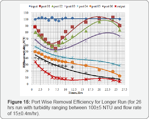
The port wise turbidities were monitored during
filter run (F. R.) with influent turbidity 20±3NTU. Constant flow rate
of 15±0.4m/hr was employed. The F. R. was carried out for 19 hrs. The
average effluent turbidity obtained was 4.2 NTU. So, the removal
performance was good enough in view of target turbidity set (10 NTU).
The total head loss developed was 22.5cm after 19 hr therefore the run
could have been extended further, as the effluent turbidity was also
significantly less than target turbidity.
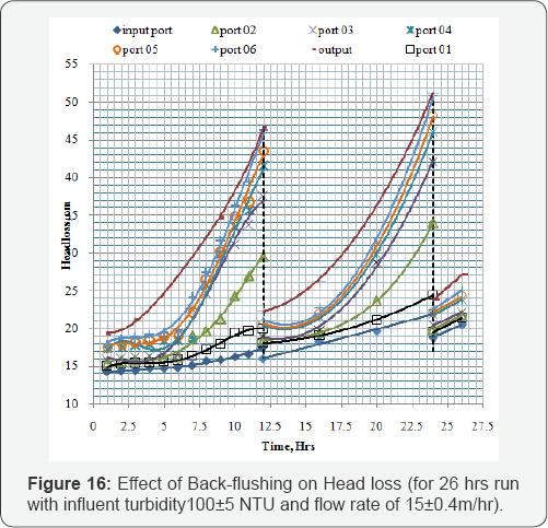
As seen from Figure 16,
it can be understood that turbidity removal is throughout filter depth,
though it is more significant in middle lower portion of total media.
For some other F. R., URF was operated for duration
of 26hrs; and during this time interval port wise turbidities were
monitored (Figure 15).
Back flushing was adopted after ever 12 hrs for improving performance
of URF for this filter run. While operating this filter run influent
turbidity of 100±5 NTU and constant flow rate of 15±0.4m/hr was
employed.
Observing trend of turbidity removal in this filer
run, it can be understood that after each back flushing interval (i.e.
every 12 hrs) there is moderate change in removal efficiency of URF.
However, as filter run proceeds turbidity keeps on decreasing. The Figure 16
gives relationship between head loss and time. Here also effect of back
flushing can be seen notably. After each back flushing phase there is
fall in head-loss and gradually it increases. The recovering of utilized
head has significantly positive impact since it helps in extending
duration of filter run and periodic back-flushing assists in keeping the
bed reasonably clean. At the end of the filter run maximum head loss
observed after 26hr was just 27.1cm. Periodic back flushing is required
to prevent heavy accumulation of solids in the roughing filter. This
will reduce deterioration of effluent due to detachment and in
minimizing head losses too.
Conclusion
Based on the present study, it is feasible to render
certain inferences regarding behavioral aspects of URF, deployed as an
alternative for pretreatment of water. Further, the recommendations for
design and operating parameters for URF are also put forth based on the
experience of performance URF.
General features of URF
o Up flow roughing filtration is found to be viable
for pretreatment of water. The URF is found to function consistently for
long duration without special requirements of operating skills. So, the
present study corroborates its deployment in rural water supply schemes
where treatment plant capacities are small; and skilled operators not
available.
o The URF demonstrated true depth filtration as head
loss developments were moderate and there was no incidence of clogging
of the bed.
o Clean bed head losses are insignificant in URF due
to large grain size and porosities. Theoretical head losses computed
using Ergun's formula, are comparable with observed head losses.
o The initial effluent quality was found to be poor
during ripening. Ripening periods are found to be reasonably smaller
(3min) for lower flow rates (5m/hr) and lower influent turbidities
(26±0.5). Ripening periods are found to be larger (60min) for larger
flow rates (20m/hr) and larger influent turbidities (100±1).
o Head losses in URF during operation are inversely
proportional to flow rate and directly proportional to influent
turbidity. However, the head-loss development in UFR is moderate due to
large grain size and porosities. In general head loss is not the run
termination criterion for URF.
o influent turbidity. However, the head-loss
development in UFR is moderate due to large grain size and porosities.
In general head loss is not the run termination criterion for URF.
o The head lost during operation can be recovered
through back-flushing periodically. So, back-flushing results in
extending the URF runs.
For More Open Access Journals Please Click on: Juniper Publishers
Fore More Articles Please Visit: Civil Engineering Research Journal
Fore More Articles Please Visit: Civil Engineering Research Journal


Comments
Post a Comment