Nonlinear Dynamic Response Analyses of Nuclear Containments- Juniper Publishers
Juniper Publishers- Journal of Civil Engineering
Abstract
The shear strength of shell elements in nuclear
containments strongly depends on the softening behavior of concrete
struts in the principal compression direction due to principal tension
in the perpendicular direction. In the past, the Cyclic Softened
Membrane Model (CSMM) which incorporates the effect of concrete
softening has been developed to accurately predict the response of
wall-type structures subjected to seismic loading. Recently, a
CSMM-based shell element was developed that extended the applicability
of CSMM to shell-type structures. In this paper, a nonlinear dynamic
response analyses of a 1/13th scale nuclear containment
subjected to seismic margins and near-fault earthquakes are carried out
using the Simulation of Concrete Structures Software developed at the
University of Houston by using OpenSees as a platform. The time history
of response acceleration, first yielding of reinforcement, ultimate
state and the corresponding safety factors are critically examined by
the analytical data. The input acceleration and response acceleration
for both far-field and near-field earthquakes were compared. The
far-field response acceleration was found to be higher than the response
acceleration of near-field, which was attributed to near-field input
accelerations having restricted frequency content in lower frequencies
as compared to far-field input accelerations.
Keywords: Nonlinear; Dynamic; Nuclear containment; Shell; FEM; CSMM
Abbreviations:
CSMM: Cyclic Softened Membrane Model; RC: Reinforced Concrete; FEM:
Finite Element Method; SCS: Simulation of Concrete Structures
Introduction
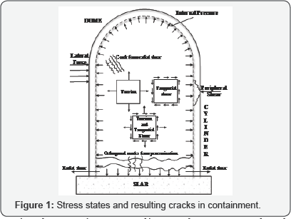
A nuclear containment vessel is a complex structure
and needs significant safety requirements, such as pressure resistance,
radiation leaking prevention, seismic and impact protection, etc.
Considered to be a competitive material that satisfies the safety
requirements of the containment structure, reinforced concrete has been
used extensively from the beginning of the nuclear power industry. With
the large dimensions of the structure, a reinforced concrete nuclear
containment vessel often contains large sections and large diameter
steel bars. The reinforced concrete nuclear containment vessel is
classified as a shell-type structure with complex stress conditions, as
shown in Figure 1,
which involve various states. For example, internal pressure due to a
leakage accident could produce large bi-axial tension, and an earthquake
action could lead to seismic (tangential) shear, which has become a
major design consideration. Airplane collisions, missile attacks, and
other high local loads could lead to punching (peripheral) shear
Banerjee & Holley [1].
The classical analysis of the shell structures
includes two applied theories: the membrane theory and the bending
theory Similar to plates, the shell structures can carry lateral loads
by developing two bending moments and a twisting moment. The shell
structures also can carry compressive and tensile loads in their plane
by developing membrane actions Cook [2].
Compared to other types of shell structures, the
structural behavior of RC shell structures is difficult to predict,
especially when they are subjected to earthquake loading. The seismic
response of RC shell structures is highly inelastic, which is caused by
the highly nonlinear behavior of materials including the nonlinear
constitutive relationships of reinforcement and concrete under reversed
cyclic actions. However, from the structural point of view, a whole RC
shell structure can be visualized as assemblies of many RC elements.
This concept makes it easier to analyze this complex structure in which
the finite element analysis combined with the proper constitutive models
for concrete and reinforcing steel make it a powerful tool. The key to
the rational analysis of the RC structure is to understand the behavior
of one element isolated from the structure. Once a rational model is
developed to predict the behavior of one element, this rational model
can be incorporated into a finite element program to predict the
behavior of the whole structure under different kinds of loading.
Because of the complexity of testing conditions, in
an element-based study only a few research groups with special testing
equipment could conduct an experimental study of shell elements. Two
famous systems for testing RC shell elements are the Shear Rig developed
by Vecchio & Collins [3] at the University of Toronto and the Universal Panel Tester developed by Hsu & Belarbi, et al. [4]
at the University of Houston. Using the experimental results of the
panel tests, many constitutive models for reinforced concrete have been
proposed. The models are the Compression-Field Theory and Modified
Compression Field Theory by Vecchio & Collins) [5], Vecchio & Collins [6]; Disturbed Stress Field Theory by Vecchio [7]; Rotating-Angle Softened Truss Model (RA-STM) Belarbi & Hsu [4], Pang & Hsu[9] , the Softened Membrane Model (SMM) Hsu & Zhu [10], and the Cyclic Softened Membrane Model (CSMM) Mansour & Hsu [11].
They all satisfy Navier's three principles of mechanics of materials
and, thus, are rational. Among these constitutive models, the CSMM is
the most versatile and accurate. The CSMM is capable of predicting the
cyclic shear behavior of reinforced and prestressed concrete membrane
elements including the stiffness, ultimate strength, descending branch,
ductility, and energy dissipation.
Over the past decades, researchers at the University
of Houston have made significant contributions to the finite element
analysis of reinforced concrete elements and members subjected to shear.
Using the OpenSees framework, they developed a two-dimensional (2D)
reinforced concrete element, the RCPlaneStress Quadrilateral element,
which is based on the CSMM. The UH researchers implemented the element
into the Simulation of Concrete Structures (SCS), which is a nonlinear
finite element computer program. SCS showed a significant capability of
simulating the behavior of RC structures such as shear walls, bridges
columns subjected to static, reversed cyclic, and dynamic loading.
Although the SCS program with RCPlaneStress
Quadrilateral element based on the CSMM is capable of accurately
predicting the behavior of concrete structures, it, however, cannot be
used to model RC shell structures. Because the RC shell structures are
three-dimensional (3D), problems with complex loading conditions while
the RCPlaneStress Quadrilateral element can only be valid for 2D
problems. Therefore, a new shell element based on CSMM was developed by
Luu et al. [12]
and implemented into the finite element program SCS-3D to predict the
nonlinear behavior of RC shell-type structures. The research was
conducted by a model-based simulation approach that included four steps:
modeling, implementation, validation, and application. The CSMM-based
shell element was developed by utilizing formulation of the degenerated
shell theory with layered approach [13],
and taking into account the Cyclic Softened Membrane Model (CSMM). The
formulations of CSMM were extended from 2D to 3D so that they could be
implemented into each layer of the shell element.
The capacity of the analytical models in predicting
the behavior of RC shell structures using the developed CSMM- based
shell element was verified by experimental data from several large-scale
tests of RC shell structures subjected to monotonic, cyclic and seismic
loadings. The structures selected for validations included a panel
tested under pure shear Mansour & Hsu [14]; Pang & Hsu [15], panels tested under pure bending and combination of shear and bending Polak & Vecchio [16], a 3D RC cylindrical tank Maekawa, Okamura & Pimanmas [17], a RC shear wall, and six RC rectangular and circular hollow bridge piers Yeh & Mo [18]; Yeh, Mo, & Yang [19].
Furthermore, the developed CSMM-based shell element
was applied to investigate the structural behavior of the reinforced
concrete nuclear containment vessel under reversed cyclic loading. Two
1/13-scaled RCCV specimens were designed and tested at the National
Center for Research on Earthquake Engineering (NCREE). The behaviors of
the specimens were experimentally investigated. The nonlinear finite
element analysis of the nuclear containment vessel specimens was
conducted through the finite element program SCS-3D using the proposed
CSMM-based shell element. The analytical model accurately predicted the
behavior of the specimens including the cracking patterns, the first
yielding points, yielding distributions of the steel bars, and the
overall hysteretic loops of the load and displacement curve [29].
Under seismic loading, the nuclear containment vessel
is subjected to cyclic flexural, axial and Shear forces. Shear behavior
is an important consideration in a concrete containment wall, and a
realistic assessment of shear strength and stiffness across cracks is
essential to the design and analysis of concrete structures. Because of
its critical importance to nuclear safety, the containment structure
must be able to maintain structural integrity while undergoing
simultaneous stresses of internal pressure, earthquake action, and/or
high local loads. Under these conditions, the accurate assessment of
shear behavior poses a difficult design and analysis problem Leombruni
et al.[20].
Therefore, the SCS-3D finite element program is used to perform
analyses of the 1/13-scale RCCV specimens under real seismic loadings.
Approach
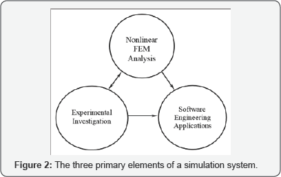
As the traditional approach such as analytical
methods and experimental methods are and still will be essential,
computer simulation has now become a third path to knowledge in many
fields. Nonlinear FE method is certainly one of the most important
approaches to computer simulation in structural engineering. Meanwhile,
the best form of realization and representation of a simulation
methodology may be its implementation as computer software. Thus,
software engineering issues such as software reuse, component-based
software development, and internet computing application to engineering
software are also crucial for the simulation system to be successful.
The relationships among these approaches are as depicted in Figure 2.
This research was conducted by a model-based
simulation approach that included four steps: modeling, implementation,
validation, and application. The National Science Foundation proposed an
initiative called Model-Based Simulation (MBS), whose objective is to
replicate the behavior of a complex system under loading and
environmental condition. The core concept of MBS lies in the area of
modeling (science), simulation (computing), and validation
(experimentation) (Chen 2000), and is believed to be the future
direction of structural engineering research.
According to Chen (2000), the development of
model-based simulation for any civil engineering facility must involve
the three steps: 1) mathematical modeling, 2) solution algorithm, and 3)
software engineering. The contents of this research can be expressed in
terms of the three steps:
a. Mathematical Modeling: Refined constitutive models
of RC materials are studied and used to rationally account for the
behavior of the materials subjected to reversed cyclic loads.
b. Solution Algorithm: Force-based non-linear fiber
FE analysis is used to simulate the overall behavior of RC frame
structures subjected to earthquake excitations. Artificial neural
networks are employed to provide large-scaled quick estimation.
c. Software Engineering: An object-oriented
programming framework is adopted to enhance software productivity,
portability, and general quality, and a complete set of nonlinear FE
software is developed.
Elements and Materials
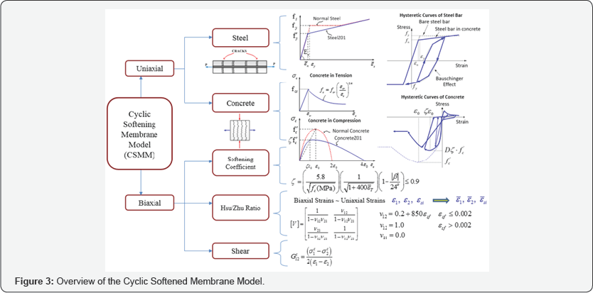
The constitutive model used is based on the Cyclic Softened Membrane Model proposed by Mansour & Hsu [21], as shown in Figure 3.
The model is capable of accurately predicting the pinching effect, the
shear ductility and the energy dissipation capacities of RC members.
CSMM included the cyclic uniaxial constitutive relationships of concrete
and embedded mild steel. The characteristics of these concrete
constitutive laws include (1) the softening effect on the concrete in
compression due to the tensile strain in the perpendicular direction;
(2) the softening effect on the concrete in compression under reversed
cyclic loading and (3) the opening and closing of cracks, which are
taken into account in the unloading and reloading stages. The
characteristics of embedded mild steel bars include (1) the smeared
yield stress is lower than the yield stress of bare steel bars and the
hardening ratio of steel bars after yielding is calculated from the
steel ratio, steel strength and concrete strength and (2) the unloading
and reloading stress-strain curves of embedded steel bars take into
account the Bauschinger effect.
Zhong [22]
formulated a two-dimensional reinforced concrete plane stress membrane
element based on the Cyclic Softened Membrane Model to simulate the
behavior of reinforced concrete shear walls subjected to static,
reversed cyclic and dynamic loading. Recently, luu et al. [12]
implemented a new shell element, the so-called CSMM-based shell
element, into the SCS program. The element was developed based on the
Cyclic Softened Membrane Model Mansour & Hsu [21] and the formulation of an 8-node Serendipity curved shell element Ahmad, Irons et al. [24] with a layered approach Scordelis & Chan [25].
A summary of the material models and elements that are developed by
researchers at the University of Houston and implemented in OpenSees is
shown in Table 1.

Implementation
Many available commercial finite element programs are
available for the nonlinear analysis of shell structures, i.e. ABAQUS,
ANSYS, ADINA, etc. However, not many of them have good constitutive
models for reinforced concrete, especially models that can account for
shear failure. These commercial programs usually are not open-source
and, thus, put limitations on users in developing their material
constitutive models. In recent years, the Pacific Earthquake Engineering
Research (PEER) Center at the University of California, Berkeley
developed an open/free finite element framework using object-oriented
languages (C++), OpenSees (Open System for Earthquake Engineering
Simulation) OpenSees [26].
OpenSees is an object- oriented framework for simulation applications
in earthquake engineering using finite element methods. Key features of
OpenSees include the interchangeability of components and the ability to
integrate existing libraries and new components into the framework
without the need to change the existing code. These features make it
convenient to implement new classes of elements, materials, and other
components.
Under the OpenSees framework, each finite element
analysis consists of four main types of objects: Model Builder
object,Domain object, Analysis object, and Recorder object, as shown in Figure 4.
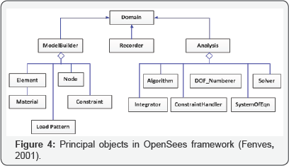
Under this framework, if a new type of element or new
material is to be introduced, a new corresponding class of objects can
be added to the OpenSees according to the designated specification of
the framework without changing the existing code. This is because of the
interface, which is defined in the core components (abstract classes),
is minimal to make adding new component classes easier but large enough
to ensure that everything is required can be accommodated (Fenves,
2005).

Over the past decades, researchers at the University
of Houston have made significant contributions to the finite element
analysis of RC elements and members subjected to shear. Using the
OpenSees framework, the Cyclic Softened Membrane Model was implemented,
and Zhong [22]
developed a nonlinear finite element computer program, the Simulation
of Concrete Structures (SCS). A 2D reinforced concrete plane stress
material module, the RCPlaneStress, and three uniaxial material modules
of concrete and steel, ConcreteZ01, ConcreteZ02, and SteelZ01, were
first implemented into SCS program, as shown in Figure 5.
SCS became a powerful FE tool to simulate the behavior of reinforced
concrete elements/members/structures subjected to static, reversed
cyclic, and dynamic loading.
Recently, Luu & Mo et al. [12]
implemented a new shell element, the so-called CSMM-based shell
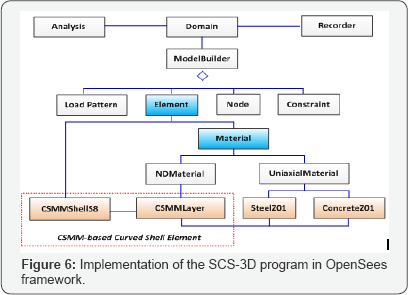
element, into the SCS program. The element module CSMMShellS8 represents
the CSMM-based shell element. The nDMaterial module CSMM Layer was
created to incorporate the formulation of the tangential material matrix
for concrete and steel into each layer of the developed shell element
as shown in Figure 6.
The CSMMLayer was connected with the two uniaxial Material modules,
SteelZ01 and ConcreteZ01, to determine the material constitutive matrix
and calculate the stress of the elements at each layer. Two uniaxial
Material modules for concrete (ConcreteZ01) and steel (SteelZ01) were
created previously based on the uniaxial constitutive relationship of
concrete and steel in CSMM Zhong [22].
Validation
The developed nonlinear finite element program SCS is verified by the experimental data in the literature Gao [27]; MA & Zhong [28].
Three types of structures, including framed shear walls subjected to
axial load and reversed cyclic loading, Low-rise shear walls subjected
to seismic loading, and nuclear containment subjected to reversed cyclic
loading, are analyzed.

Note: Cross section of columnS and beams is
'lb2.4mmX152.4mm. Wall thickness is 76.2mm. Diameter of W2 wires is
4.14mm. D3 bar and' #2 bar have an approximately the same yielding
strength of 14 KN. Longitudinal steel in columns and beams is 6#4 with
longitudinal steel percentage of 3.33%. , A is the total area of the
cross section of column and beams.
1MPa=14bPsi, 1Kips=4.448KN, 1inch=2b.4 mm.
*The three specimens with asterisks have seismic hoops (31.7bmm. spacing) in the potential plastic-hinge regions.
** Panel steel in both the vertical and the horizontal directions.
Framed shear walls subjected to reverse cyclic loading:A
complete test program of nine shear walls tested by was analyzed using
the developed program. Tests on nine 1/3-scale framed shear walls,
subjected to a constant axial load at the top of each column and a
reversed cyclic load at the top beam, were performed at the University
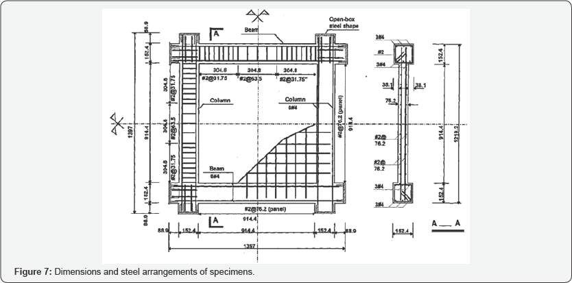
of Houston. The wall dimensions were 914.4mm by 914.4mm with a thickness
of 76.2mm. The cross-section of the boundary columns was 152.4mm
square. Figure 4
demonstrates the details of dimensions and reinforcement of the
specimens. The bottom left and right corners of the specimen were
supported by a hinge and a roller, respectively. The test program
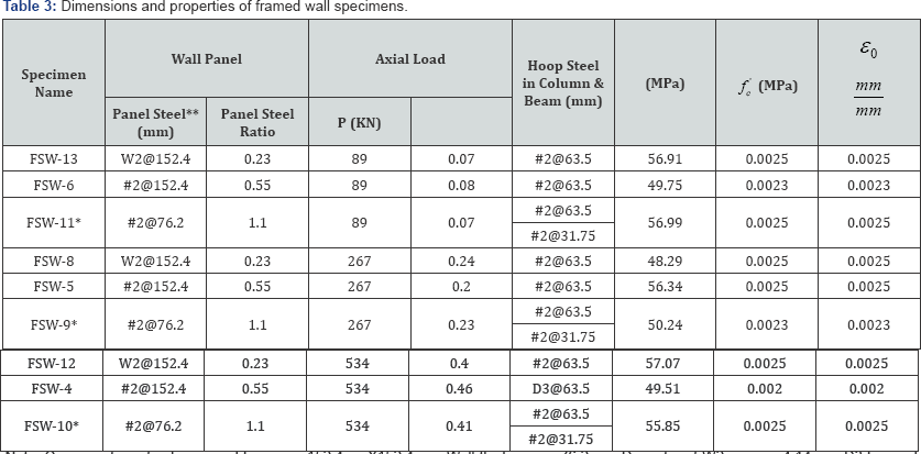
includes nine specimens to study two variables as shown in Table 2.
The first variable is the axial load ratios on the columns (P/Po):
0.07, 0.2 and 0.4. The second variable is the steel ratio in the wall
panel which varied from 0.25% to 0.55% to 1.1%. The actual wall steel
ratio and axial load ratio of each specimen are listed in (Table 3) (Figure 7).
Figure 8
shows the finite element mesh of the specimens. The wall panel was
modeled as nine Quadrilateral elements with RCPlaneStress material. The
steel ratio and the steel grid orientations of the wall panel were
defined in the RCPlaneStress material. SteelZ01 and ConcreteZ01 were
used to create the uniaxial constitutive laws of steel and concrete,
respectively.
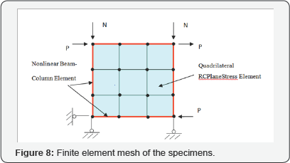
The present library of OpenSees has the fiber element
named Nonlinear Beam Column capable of modeling the RC beams and
columns. In this finite element mesh, each of the boundary beams and
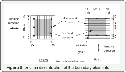
columns was modeled as three Nonlinear Beam Column elements. Each fiber
elements were defined with 3 control sections. Figure 9 gives the configuration of the section discretization.
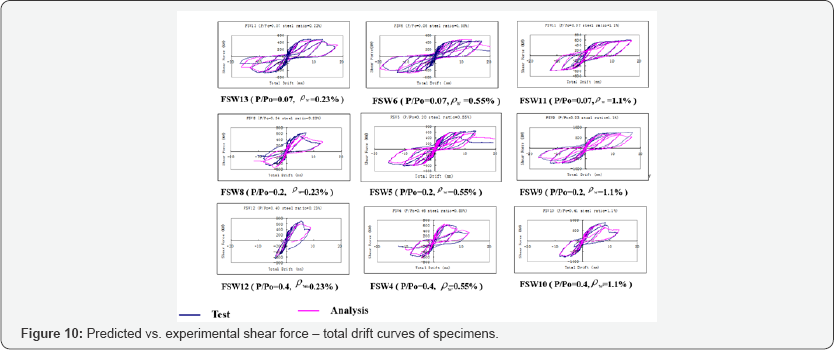
The analytical results of the sheer force-drift relationships of nine shear walls are illustrated by the solid purple curves in Figure 10.
For easy comparison, the corresponding experimental results, indicated
by the solid blue curves, are also plotted in the figures. It can be
seen from the comparison that for the primary curves (backbone curves)
the predicted outcomes agree very well with the experimental results in
the initial stiffness, yield point, and ultimate state for all the
specimens.
Low-rise shear walls subjected to seismic loading:
Four low-rise shear walls with a height-to-width ratio of 0.5 were
tested on a shake table. The specimens were designed with a scale factor
of 1:2 according to the capacity limit of the shake table. Four
specimens had the same dimensions of 700mm in height, 1400mm in length,
and 60mm in thickness.
The four specimens were identified as ST1, ST2, ST3,
and ST4, respectively. The labels of all specimens begin with the
letters "ST," signifying that the specimens were tested on a shake table
subjected to a seismic excitation. The variables in the test program
were:
a. Concrete strength.
b. Boundary elements and
c. Steel grid orientation in the wall panel.
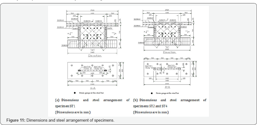
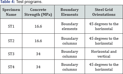
Details of the four specimens are listed in Table 4, wherein the test parameters are indicated. The dimensions and steel arrangements of the four specimens are shown in Figure 11.
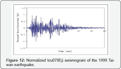
The tcu078Eji seismogram of the 1999 Taiwan
earthquake was used as the ground motion acceleration for the shake
table. The normalized seismogram is shown in Figure 6.
In each test run, a scale factor was applied to the input ground motion
acceleration such that the Peak Ground Acceleration (PGA) would reach
the predetermined value Figure 12.
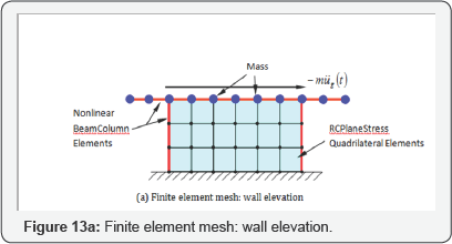
Nonlinear dynamic analyses were conducted on the four
specimens using the proposed nonlinear finite element program SRCS. As
illustrated in Figure 13a,
the finite element mesh of the structure was divided into three zones:
the web panel, the boundary elements, and the top slab. The wall panel
was modeled using 18 RCPlaneStress quadrilateral elements. Each of the
two boundary elements was modeled using 3 Nonlinear Beam Column
elements, and the top slab was modeled using 8 Nonlinear Beam Column
elements.
Only one type of RCPlaneStress Quadrilateral element
was defined in the finite element model of each specimen, because the
steel grid orientations and spacing were the same in the wall panel, and
the material properties could be assumed to be uniformly distributed.
According to steel grid orientations in the four specimens, the steel
grid orientations in the RCPlaneStress Quadrilateral elements of
specimen ST1, ST2 and ST4 were defined at 45 degrees and 135 degrees
with respect to the horizontal direction. The steel grid orientations in
the RCPlaneStress Quadrilateral element of specimen ST3 was defined in
the horizontal and vertical directions. Uniaxial material modules
SteelZ01 and ConcreteZ01 were used to create the constitutive laws of
uniaxial steel and concrete and to relate them to the reinforced
concrete material RCPlaneStress.
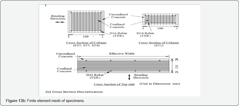
The boundary element at each side of the wall was
modeled using 3 NonlinearBeamColumn elements. Each Nonlinear Beam Column
element was defined with 3 control sections. As shown in Figure 13b,
the white cells represent the unconfined concrete fibers, the gray
cells represent the confined concrete fibers, and the black cells
represent the reinforcing steel fibers. Concrete01 was used to define
the concrete fibers in the cross section. The stress and strain of the
confined concrete was determined based on the modified Kent and Park
model. SteelZ01 was used to define the steel fibers in the cross
section.
The calculated response time history of the four
specimens at the test runs of elastic, steel yielding, and post yielding
states are compared with the measured response time history.
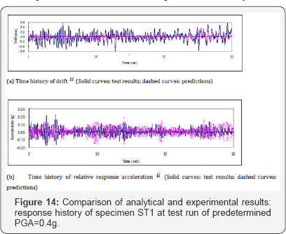
Only specimen ST1 will be discussed here to avoid
repetition. The details of other specimens can be found out from the
research paper by MA et al. [28].
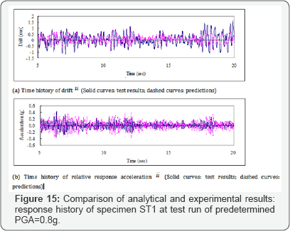
For specimen ST1, the time history of the predicted drift and relative
response acceleration for test runs with a PGA of 0.4g, 0.8g and 1.2g
are compared with the experimental results in (Figures 14-16)
respectively. The comparisons are presented in the first 20 seconds
where the response of displacement and acceleration reached the most
significant values in the entire time history.
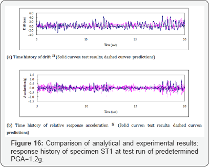
The calculated time history of drift and relative
acceleration of the four shear walls agree well with the experimental
curves in the test runs of the elastic stage, the steel yielding stage,
and the post-yielding stage. The good agreement validates the nonlinear
dynamic analysis capability of the proposed finite element program SRCS.
Nuclear containment structure subjected to reversed cyclic loading: The
experimental program included the construction and testing of two
1/13-scale nuclear containment specimens. These specimens were designed
to investigate the behavior of an RC nuclear containment isolated from a
nuclear power plant and subjected to the gravity and earthquake loads.
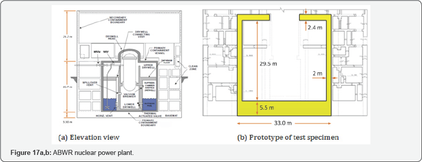
The specimens were designed based on the prototype of an Advanced
Boiling Water Reactor (ABWR) nuclear containment structure (Figure 17a). The real-size containment has a height of 29.5m, a radius of 15.5m (center-line dimension) and a thick wall of 2.0m (Figure 17b).
Each specimen included three parts: the main containment, top block and
bottom block. The bottom block simulated the rigid foundation while the
top block simulated the rigid floor system. These blocks were designed
with steel plate boxes filled with concrete and a large amount of
reinforcing steel. These blocks were designed conservatively to avoid
significant deformation occurring in the blocks so that the nonlinearity
occurred only in the containment walls during the tests. Rotations of
the top and bottom blocks in the vertical plane were prevented during
the test to ensure the containments deforming in a double-curvature
manner during the tests. The dimensions of the test specimens are shown
in Figure 18.
The containments had a height of 2.25 m and a radius of 1.175m
(centerline dimension). The outer and inner diameters of the
containments were 2.5 m and 2.2 m, respectively. The thickness of the
containment was 0.15m. The top and bottom blocks of the specimens had a
cross section of 3.5m x 3.5 m and a depth of 0.73m.


The reinforcement arrangement in the specimens is illustrated in Figure 19.
Four layers of vertical and horizontal steel rebars were uniformly
placed along the thickness of the containments. The steel rebars were
uniformly distributed around the perimeter and along the height of the
test containments with the same spacing. The percentage of the
reinforcement ratio in the containment of Specimen No. 1 was 2% in both
the vertical and horizontal directions (Figure 19a).
The reinforcement arrangement of Specimen No. 2 was almost identical to
Specimen No. 1 except that more vertical steel rebars (dowel bars) were
added to each end of the containment to enhance its shear sliding
capacity, resulting in the vertical reinforcement ratio of 4% in each of
these two ends (Figure 19b).
The cut-off points of the additional vertical steel rebars were
arranged in a jagged manner to prevent cracking within the cutoff
regions. The centerline of the zigzag curve was at a quarter of the
containment height. The vertical bars in the containments were
continuous without lap splices. The clear concrete cover over the
vertical bars was 17mm. The details of dimensions and material
properties of the specimens are summarized in Table 5.
The compressive strengths of concrete of Specimen No. 1 and Specimen
No. 2 at the testing date were 37.0 MPa and 43.3 MPa, respectively. Both
specimens used the same steel bars taken from the same batch. The
yielding strength of the vertical and horizontal steel bars was 379 MPa
and 376 MPa, respectively.

Note: = Compressive strength of concrete; = Diameter
(Center-to-center); = Thickness; = Net height; = Yielding strength of
steel; = Ultimate strength of steel; = Steel ratio in vertical
direction; = Steel ratio in horizontal direction.
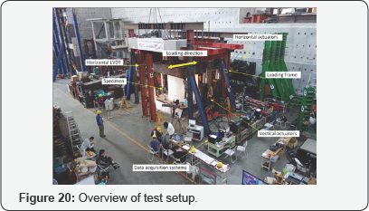
At the NCREE Laboratory in Taiwan, the test specimens
were subjected to horizontal loading up to their maximum capacity with a
set of specially built steel loading frames. The test setup was used to
simulate gravity and the lateral and vertical earthquake loads. Figure 20
gives an overview of the test setup with various equipment components,
including the horizontal actuators, vertical actuators, L-shape steel
loading frame systems and the specimen. The specimens were loaded
axially using four 1000-kN-capacity vertical hydraulic actuators. Pin
connections were used at the end of the vertical actuators. The
simulated lateral earthquake load was applied by eight 1000-kN-capacity
horizontal actuators under displacement control. The horizontal
actuators were bolted to a rigid concrete reaction wall and the L-shape
loading frame so that the center of the loading axis passed through the
specimen's mid-height. The specimens were connected to the strong
concrete floor using high-strength all-thread steel rods that went
through the foundation of the specimens. The loading frame was allowed
to move freely in the vertical plane. Additional steel frames bolted to
the solid floor were placed on the north and south sides of the specimen
to prevent the horizontal out-of-plane displacement. During the tests,
the containment specimens were subjected to constant vertical axial
loads and horizontal reversed-cyclic load until failure.
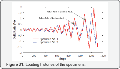
The first step of the loading protocol program was to
apply an axial load that would remain constant during the test. The
total initial vertical load equaled 1.6% of the axial concrete capacity (
) of each specimen, where is the compressive strength of concrete and
is the nominal area of the specimen. The axial concrete capacity was
dependent on the compressive strength of the concrete; consequently, the
total initial vertical load varied for each specimen. After the axial
load had been applied, a reversed-cyclic load was added by the eight
horizontal actuators under drift ratio control. First, the test
specimens were subjected to several cycles of small drift ratios for
warming up. Then, the tests were performed by using the loading history
consisting of the following drift ratio cycles: 0.1%, 0.15%, 0.25%,
0.37%, 0.5%, 0.75%, 1.0%, 1.5%, and 2.0% (Figure 21).
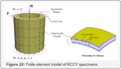
Analytical Model: The specimens were modeled using the finite element mesh illustrated in Figure 22.
For each specimen, the cylindrical wall of the vessel was defined by 40
CSMM- based shell elements. The steel layers were defined at the exact
locations of the steel in the cross section of the specimen. In Specimen
No. 1, all shell elements were assigned with 2% of reinforcement in
both the vertical and horizontal directions. The percentage of steel
used in shell elements of Specimen No. 2 was almost identical to
Specimen No. 1, except the shell elements located within the distance of
one-fourth of the net height at the top and bottom of the specimen were
assigned with 4% of vertical reinforcement. The top block of each RCCV
specimen was defined as a rigid body by using ten 8-node linear-elastic
shell elements with high stiffness. For the boundary conditions, all
nodes at the bottom of the model were constrained to prevent any
translations or rotations. Equal horizontal and vertical loads were
applied at all nodes along the perimeter at the height level of the
specimen based on the assumption that the loads were uniformly
distributed. The axial loads acting on the cap were applied with the
direction and magnitude of the loads remaining constant in the analysis.
The horizontal loads were changed according to the displacement control
scheme.

Note: Vcr,Δcr= Horizontal load and drift ratio at first cracking; Vyv,Δyv= Horizontal load and drift ratio at first yielding of vertical rebar;  =Horizontal load and drift ratio at first yielding of horizontal rebar; ,
  = Horizontal load and drift ratio at peak load in the positive direction;
 =Horizontal load and drift ratio at first yielding of horizontal rebar; ,
  = Horizontal load and drift ratio at peak load in the positive direction;
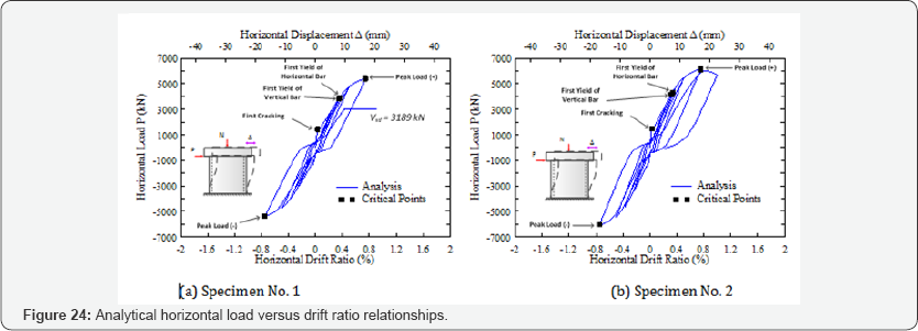
The experimental and analytical horizontal load versus drift ratio relationships of the test specimens are shown in Figure 23 and Figure 24,
respectively. These curves illustrate the load resisting mechanism of
the nuclear containment vessels. Five critical points were indicated in
the horizontal load versus drift ratio curve representing the first
cracking of concrete (Point 1), the first yielding of vertical and
horizontal steel bars (Point 2 and Point 3) and the peak loads in the
positive and negative directions (Point 4 and Point 5) in each specimen.
The values of the load and drift ratio at the critical points of the
specimens are summarized in Table 6.
Overall, the analytical results had a good correlation with the
experimental data. The analytical model accurately predicted the
structural behaviors in both the positive and negative directions,
including the primary backbone curve, the first cracking, the initial
stiffness, the yielding distribution of steel bars, and the unloading
and reloading paths as well as the pinching effect of the specimens.
The nonlinear finite element analysis of the nuclear
containment vessel specimens was conducted through the finite element
program SCS using the developed CSMM-based shell element. The
analytically predicted results compared very well with the experimental
data. Overall, the primary backbone curves, the initial stiffness, the
peak strength, the descending branch, the yielding distributions and the
failure characteristics were accurately predicted. The analytical
hysteresis loops also provided accurate measurements of the pinching
effect, and the energy dissipation capacity.
Nonlinear Dynamic Response Analyses of Nuclear Containments
The Simulation of Concrete Structures program was
used to perform a nonlinear dynamic response analyses on the 1/13th
scale nuclear containment vessel. The specimen details and dimensions
are described in Section 5.3. The analyses of the nuclear containment
specimen are carried out with two types of earthquake excitations: The
El Centro earthquake time history for far-field seismic analyses and The
TCU052 earthquake time history for near-field seismic analyses. The
normalized input ground acceleration for both the earthquakes is shown
in Figures 25 & 26.


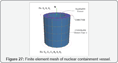
Analytical Model: The specimens were modeled using the finite element mesh illustrated in Figure 27.
The cylindrical wall of the vessel was defnied by 40 CSMM-based shell
elements. For the boundary conditions, all nodes at the bottom of the
model were constrained to prevent any translations or rotations. Ten
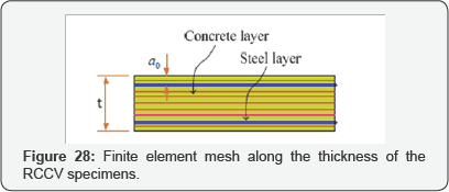
layers of concrete and two layers of steel were assigned for each
element using the CSMM Layer material module, as shown in Figure 28.
The steel layers were defined at the exact locations of the steel
within the cross section of the specimen. All shell elements in the
specimen are assigned with 1% of reinforcement in both vertical and
circumferential directions.
Far Field Seismic Analysis: The El Centro
earthquake time history is selected as input earthquake excitation for
far field seismic analysis of the nuclear containment specimen. In Phase
1, using one g as the peak ground acceleration, the mass (m) is
increased to achieve the ultimate state (i.e. when the compressive
strain of the concrete reaches 0.003). The response acceleration of the
nuclear containment is shown in Figure 29. The input ground acceleration and output response acceleration are compared in Figure 30.


In Phase 2, the mass obtained from the ultimate state
is kept constant and the peak ground acceleration (PGA) of the input
earthquake excitation is decreased to obtain the first yielding
behavior. From the far field seismic analysis, it is predicted that the
ultimate state is achieved when the mass is increased to the 5.5 times
of its initial mass at a PGA of 1.0g and the first yielding state is
achieved at a PGA of 0.65g. The output acceleration for 0.65g PGA is
shown in Figure 31. The response acceleration for yielding state and ultimate state is compared in Figure 32.
The seismic margin can be calculated as the ratio of the PGA at the
ultimate state to the PGA at the first yielding state. From the far
field, seismic analysis of nuclear containment specimen, the seismic
margin is calculated as 1.54.
Near Fault Seismic Analysis: For the near
fault seismic analysis, TCU052 earthquake time history is selected as
the input earthquake excitation to the nuclear containment specimen. In
Phase 1, the mass (m) is increased to achieve the ultimate state (i.e.
when the compressive strain of the concrete is 0.003). The response
acceleration of the nuclear containment is shown in Figure 33. The input ground acceleration and output response acceleration are compared in Figure 34.


In Phase 2, the mass obtained from the ultimate state
is kept constant and the peak ground acceleration of the input
earthquake excitation is decreased to obtain the first yielding state.
The output acceleration for 0.65g PGA is shown in Figure 35.
From the near fault seismic analysis, it is predicted that the ultimate
behavior is achieved when the mass is increased to the 5.5 times of its
initial mass at a PGA of 1.0g and the first yielding state is achieved
at 0.7 PGA. The response acceleration for yielding state and ultimate
state is compared in Figure 36.
The factor of safety can be calculated as the ratio of the PGA at the
ultimate state to the PGA at the first yielding state. From the far
field seismic analysis of nuclear containment specimen, the seismic
margin is calculated as 1.43.
Conclusions
The SCS-3D program developed at the University of
Houston could be used to create analytical models that accurately
predict the inelastic behavior of RC shell structures. Several types of
RC structures were selected to validate the analytical models including
nuclear containment vessels under reversed cyclic loading. Agreements
were obtained when comparing analytical results with experimental data.
Overall, the primary backbone curves, response history, the initial
stiffness, the peak strength, the descending branch, and the failure
characteristics were accurately predicted. Hence, the FEA program (SCS)
with the newly developed CSMM-based shell element is a very powerful
tool to investigate the seismic behavior of RC containment structures.
In this study, the SCS-3D program was used to perform
nonlinear dynamic response analyses of the 1/13th scale nuclear
containment vessels subjected to far-field and near-field input
accelerations. From the critical analysis of the analytical data, the
safety factor for far-field and near-field input accelerations was found
to be 1.54 and 1.43, respectively. The far-field response acceleration
was found to be higher than the response acceleration of near-field,
which was attributed to near-field input accelerations having restricted
frequency content in lower frequencies as compared to far-field input
accelerations.
To further validate the SCS-3D program for dynamic
response prediction, a large-scale specimen will be designed based on
the analyses reported in this paper. The specimen will be subjected to
earthquake loading using a shake-table, and the analyses results will be
compared with the experimental results.
Acknowledgement
The research described in this paper is financially
supported by U.S. Department of Energy NEUP program (Project No. CFP-
13-5282). The opinions expressed in this study are those of the authors
and do not necessarily reflect the views of the sponsor
For more articles please click on: Civil Engineering Research Journal


Comments
Post a Comment