A Note on Three-Dimensional Scattering and Diffraction by a Hemispherical Canyon, II: Normal Incident P- Point Source- Juniper Publishers
Juniper Publishers- Journal of Civil Engineering
Abstract
This paper revisits the boundary-valued problem of
the three-dimensional (3-D) scattering and diffraction of seismic
spherical waves by a hemispherical canyon in an elastic half-space, a
problem of interest to both earthquake engineers and strong-motion
seismologists. The analytical solution of normal incidence of plane
P-wave (axi symmetric) has recently been presented in [1],
using the half-range expansion of odd-order Legendre polynomials in
terms of even-order Legendre polynomials. The use of excitation by plane
harmonic waves is common in many studies of the amplification phenomena
by surface and subsurface topographies. It is assumed and reasoned that
when the spherical (3-D) and/or cylindrical (2-D) wave fronts are
sufficiently far from the earthquake source, such plane wave
approximation is adequate. The case of 2-D SH-wave source was recently
studied by [2].
The results are compared with that from plane wave incidence. It
concluded that the plane-wave approximation did provide sufficient and
reasonable approximation. This paper now uses a 3-D point source
vertically below a hemispherical canyon and studies how the results are
when compared to that of vertical plane wave incidence.
Keywords: 3-D point source; Hemispherical canyon; Elastic half-spaceIntroduction
As was discussed previously in [1],
the odd Legendre polynomial of half-range expansion can effectively
solve for the waves scattered around a 3-D hemispherical canyon in a
elastic, homogenous, and isotropic half-space with a normal plane P-wave
incidence. In this paper, the same methodology will be applied to a
similar model of canyon but the incidence is now a point-sourced P-wave.
In the perspective of seismic technology, a
point-sourced incidence is very pertinent for an earth-quake with a
shallow epicenter. For this, some numerical approaches were developed,
such as the boundary element method by [2-4], and the finite difference scheme by [5]. An analytic method of wave diffraction around a small full-space sphere was obtained by [6], in which the method of the image of a point source developed by [7]
was borrowed. Nevertheless, no effective analytic solutions for the P-
or SV-incidence in the half-space have been accomplished, because of the
difficulties of the mode conversion.
Recently in 2013, [2]
investigated the finite line source at a distance comparable to the
size of the circular alluvial valley for the out-of-plane SH waves. They
compared the resultant displacement amplitudes with those by the plane
SH-incidence and provided a positive conclusion that the plane waves are
good approximations for studies of earthquake engineering. In the end
of this paper, the same conclusion will be made based on the comparison
of results by the plane P-wave incidence and by the point-source with
various frequencies.
The Model
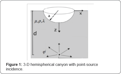
In Figure 1, a hemispherical canyon of radius a is located on the surface of the half-space, which is featured by its density ρ, and Lam'e’s constants μ , and λ
. An incident point source situates below the center of the canyon, and
is emitting longitudinal waves (P-wave) only. The distance from the
point source to the canyon center is d, which is perpendicular to the
half-space surface (Figure 1).
The spherical and rectangular Cartesian coordinates centering at the canyon center are adopted. Figure 2
shows the relationship between the Cartesian and the spherical systems.
The x-y plane is the half-space surface, and following the right-
hand-rule, the z-axis is pointing downward. The spherical coordinates is
composed by the radial distance r, the polar angle , and the azimuthal
angled ø θ . in this case is only half-ranged ,  on the half-space surface (Figure 2).
 on the half-space surface (Figure 2).
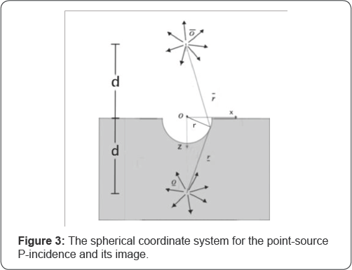
In order to describe the point-source with P-wave potential , φ(i) a spherical system originated at the point source center is also selected. In Figure 3,
O refers to the center of this new system of depth d vertically below
the center of the canyon, and r is the radial distance measured from O.
The incident potential φ(i) with harmonic frequency can then be expressed as:

where φ0 is a scale factor, with Cα the P-wave speed, is the wave number of the P-wave and h(1)0 is Hankel function of the first kind of order 0 for that the incident wave is symmetrically outward propagating (Figure 3).
 with Cα the P-wave speed, is the wave number of the P-wave and h(1)0 is Hankel function of the first kind of order 0 for that the incident wave is symmetrically outward propagating (Figure 3).
From Graf's Addition Theorem [8] and [9], φ(i) in (1) can be expanded in terms of the (r,θ,ø) coordinates with origin at the canyon center in the following form (with the time factor exp (-iωt) omitted):

where jn and h(1)n are respectively spherical Bessel function and Hankel function both of the first kind of order n, and Pn with argument u = cosθ(0 ≤ u ≤ 1) is the Legendre polynomial of order n. Note that the argument of Pn is - u
, instead of u, because the z-axis is pointing downward. Illuminated by
the image methods used in related 2D papers previously, such as [10],
the reflected wave potential due to the half-space boundary here can
now be represented by a negative (anti-symmetric) source φ(r) with respect to φ(i) relative to the half-space surface. In [10],
for SH wave, a positive (symmetric) image source was used. The O in
Fig. 3 indicates the source center of the reflected wave of distance d
vertically above the center of the canyon. Here, another polar system
originated at O is adopted for the expression of ,φ(r) then

Where r is the radial distance from O. The time factor exp(-iωt)
will again be omitted with the steady-state assumption. The Graf's
Addition Theorem is again applied to (3) to obtain the expression of φ(r) by the spherical coordinates (r,θ,ø) in the form of

The stress-free boundary conditions on the half-space surface are to be examined, to verify that φ(r) is the reflected wave of φ(i) in the half-space. These conditions at z = 0, are
σzz = Tzx = Txy = 0 (5)
Which should be satisfied by the summation of φ(i) and φ(r). In the spherical coordinate system, where φ
-term is automatically satisfied due to the property of axisymmetric
for this model so that the conditions in (5) can be expressed as


The Free-field Potential
Now it is going to show that φ(ff) naturally satisfies both half-space boundary conditions in (6).
The zero normal stress boundary condition on the half-space surface 
From [8], when r < d
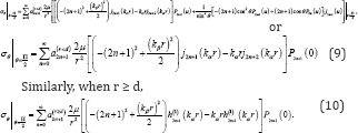
The zero shear stress boundary condition on the halfspace surface.
The general relationship between the longitudinal wave potential and the shear stress is

The equations in (7) will be re-expressed in terms of
the even Legendre polynomials, because all boundary conditions are in
half-, not full-, space. Such technique is already discussed [1].
From [1]:
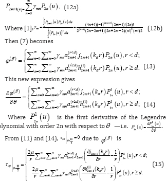
Since for the half-space surface, the shear stress boundary condition
  is again automatically satisfied.
 for the half-space surface, the shear stress boundary condition
  is again automatically satisfied.
Therefore φ(r) can be verified to be the reflected wave from the half-space (without any topography). In addition, the φ(ff) defined in (7) is the free-field wave for a point-source P-incidence in the half-space.
The Scattered Waves
The scattered waves are generated in the presence of the hemispherical canyon. The same methodology is applied as in [1] that the scattered wave's potentials will again be expressed in terms of odd Legendre polynomials only. So that

Where  is the shear wave number, with Cβ
the shear wave speed in the half-space. From (12a), the wave potentials
can also be expressed in terms of the Legendre polynomials of even
degrees as
 is the shear wave number, with Cβ
the shear wave speed in the half-space. From (12a), the wave potentials
can also be expressed in terms of the Legendre polynomials of even
degrees as
The summation of all the waves φ(ff), φ(s) , and χ(s) need to satisfy all boundary conditions on both the half-space surface and the hemispherical canyon surface, which are

All boundary conditions will be discussed as follows:
The zero normal stress boundary condition on the half-space surface .
Only the scattered P- and S-wave potentials will be taken into consideration when evaluating normal stresses since φ(ff) is already shown to satisfy this boundary condition. With (16), the P- and S- potentials with argument u = cosθ. have the following expressions of the normal stress on the half-space surface [1]:

Equation (20) is the summation over all the odd integers, n = 1,3,5,..., and Pn(0)= 0 for all r ≥ a odd n-degree Legendre polynomials, and thus for all , is always automatically satisfied. All the Eij functions above and following in the paper are listed in Appendix A.
 odd n-degree Legendre polynomials, and thus for all , is always automatically satisfied. All the Eij functions above and following in the paper are listed in Appendix A.
The zero shear stress boundary condition on the halfspace surface .
As in Boundary Condition 1, only the scattered P- and
S-wave potentials are used to satisfy the shear stress on half-space
surface. Here the expressions in (17) are adopted, and then the shear
stress by the P- and S-waves is expressed as [1]:

P1n (0) Is the first derivative of Pn (0) so that P1n
(0) is odd when n is even? Summing up along n = 1,2,3,..., the result
is definitely zero since every term is multiplying an odd function with
argument zero. Therefore conclusion could be reached that the zero shear
stress is also satisfied on the half-space surface. Now two out of the
four boundary conditions are automatically satisfied (removed), so then
the remaining two boundary conditions will next be utilized to solve for
the two sets of unknown coefficients, {A2n+1} and {C2n+1} for n = 0, 1, 2, ..., of the P- and S-wave potentials.
The zero normal stress boundary condition on the canyon surface .
The total normal stress σr is composed of the free-field wave and the scattered waves that

Thus the following relationship is then obtained:

Where σ(ff)r is the normal stress due to the free-field potential, and σ(s)r is that due to the scattered waves.
Their expressions in the spherical coordinate system are given as [1]:

Then to apply the orthogonality of odd Legendre polynomials over the half-space, (25) is simplified to be, for n = 0, 1, 2, ....

The zero shear stress boundary conditions on the canyon surface . = 0
= 0
As in to Boundary Condition 3, the zero shear stress  is from both the free-field wave and the scattered waves, so that [1]:
 is from both the free-field wave and the scattered waves, so that [1]:
Where τ(s)rθ , τ(ffrθ are respectively the shear stresses due to the scattered waves and the free-field waves. Here

After applying the orthogonality of {P12n+1 (u) }, n = 0,1,2, , that is a set of even Legendre functions, for each n the coefficients A2n+1 and C2n+1 have the following relation, for n =0, 1, 2, ....

(26) And (30) can be rearranged to be: for n = 0, 1, 2,.

Therefore, the coefficients An and Cn are given by, for n = 1, 3, 5, ...

With the determinant  Note that ɑ2n+1 should be ɑ(r<d)2n+1 of (8a) because the source is below the canyon with r = ɑ < d
 Note that ɑ2n+1 should be ɑ(r<d)2n+1 of (8a) because the source is below the canyon with r = ɑ < d
The free-field coefficients in (32) are

Surface Displacement
Vertical Displacements
The displacement amplitude at a point is a very
important assessment of the devastation at that point resulted by the
seismic waves. The vertical displacement amplitude |Uz|
will be focused here because the problem presented in this paper is an
axisymmetric problem with the longitudinal wave from a point source
vertically below the canyon. Uz Can be calculated from the spherical components Ur and Uθ ( Uφ = 0 from axisymmetry) by the transformation between the two coordinates, where,
Uz = Urcosθ- Uθ sinθ (34)
With

It is noted that, for P-point source,Uz , the vertical component, is the dominating component of motion. Here D(i)jk are the displacement-potential expressions given in Appendix A.
The displacement amplitude is the magnitude of a complexvalued displacement, so that for Uz

As was stated in (1) that φ0 is the scale
factor for the wave potentials, this scale factor should be determined
before proceeding to the numerical calculation. According to the plane
P-wave incidence, φ0 can be determined by the displacement amplitude at the original point such that such that |Uz| resulted by the free-field wave at the canyon center is always “2”.

So that |Uz| at the center of
canyon equals to number “2”, and the coe.cients of free-field potentials
can be expressed as, from (8a) and (8b):

Alternatively, an in (41a) and (41b) for the calculation of An and Cn is then given by, with r = ɑ < d,

Which contains both the source depth d, and the wave number kα
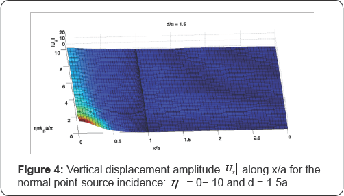

Figure 4 to Figure 9 are the vertical displacement amplitudes |Uz|along the dimensionless radial distance (x/a) for a fixed wave source location and various dimensionless frequencies η following the definition in [11], where the dimensionless frequency, η, is used:
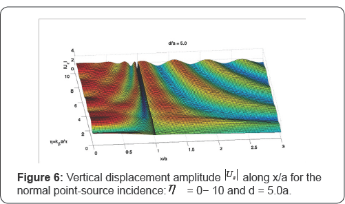

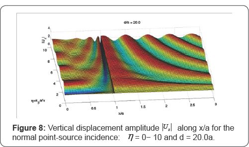
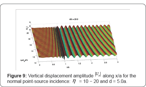

The azimuthal angle ø will play no part
because the model is axisymmetric, the axis x/a is the radial distance
r/a along any direction. ø The range of x/a from 0 to 1 represents the
distance from the center to the rim along the canyon surface when goes
from  to 0. When x/a > 1, the half-space surface is under discussion.
 to 0. When x/a > 1, the half-space surface is under discussion.
Figure 4 and Figure 5 are the vertical displacement amplitudes |Uz| respectively from η
= 0 to 10, with the same source depth of d = 1.5a. One can see that can
be as high as 20 at x/a = 0, the bottommost point of the canyon, when
is very small, but it decays quickly along the radial distance. There is
little oscillation observable on the half-space surface in the low
range when x/a > 1. With increasing , the magnitude of on the canyon
surface levels off to 2, and there are clear wave patterns on the
half-space surface showing that the particles at a relatively far
distance from the canyon center start still oscillate.
Figure 6 and Figure 7 are |Uz| respectively from η
= 0 to 10, and from = 10 to 20 with now source depth of d = 5.0a. This
time the maximum in both Figure do not exceed 3.0 from the fact that the
source is much farther from the canyon. As in Figure 4 and Figure 5
max gradually levels to 2 as increases. The wave oscillation is now
substantial, particularly in the high frequency range. At the rim of the
canyon with the ground, where x/a = 1, the “dip and spike” phenomenon,
which is described in [1], is also observed.
Figure 8 and Figure 9 contain the more intense wave motions at frequencies of η = 0-10 and η
= 10-20 respectively, when the depth of source is at d = 20a below the
origin. One notes that the amplitude of shaking is more oscillatory,
compared with the prior two sets of Figure at d = 1.5a, and d = 5.0a,
for a given η. This is because when the source is deep below the
canyon, there is now greater difference in phases and radiation
distances for any two points on the half-space surface, resulting in
greater differ in the wave amplitudes. At the low frequency range where
is η close to 0, the amplitudes along the radial distance are
almost constant and this agrees with the observation of the normal plane
P-incidence in the previous paper [1]. Moreover, the" dip and spike" phenomena at the rim (r = a) become more apparent and stable.
Next, Figure 10 consists of |Uz| four plots of at d/a = 1.5 for =0. 02, 0.5, 1.0, and 1.5, respectively. It is apparent that |Uz|
at the origin, corresponding to the lowest point of the canyon that is
closest to the source decreases with increasing . However, for a
location outside the canyon, r/a > 1, its amplitude for η = 0.02 or η = 0.5 are generally smaller than that of η = 1 or η
= 1.5 conclude, for a near source incidence with an equivalently scaled
potential, the low incident frequencies accumulate energies at the
origin, while at higher frequencies the energy is spread out by the wave
propagation. Figure 11 to Figure 13 display the vertical displacement amplitudes |Uz| at d/a=1.5, 5, and 20 for η = 0.02, 1, and 20, respectively.


It is shown from Figure 11 that for the very low frequency incidence-i.e. η
= 0.02, if the source is shallow (d/a = 1.5 here), the bottommost point
of the canyon has the most substantial deformation. While on the other
hand, if the epicenter is deep, the plots appear to have comparable
amplitudes on the half-space surface outside the canyon to those on the
canyon surface.
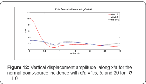
Figure 12 and Figure 13 show that when η
gets higher, the canyon bottom (where x/a = 0) still has the same high
displacement amplitude and hence the same severe damage from a shallow
source-at d/a = 1.5. Unlike the other three Figure at lower frequencies,
Figure 13 at η = 20.0 shows that the waves at the canyon and half-space surfaces are more oscillatory, even far from the canyon.
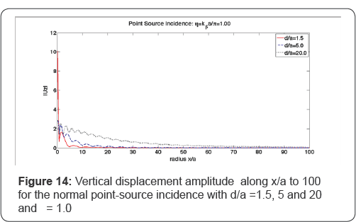
Figure 14
provides x/a = 0 to 100 to investigate the amplitudes in the
perspective of a longer range far from the canyon. Apparently, the
amplitudes resulted by a shallow wave source decay faster along the
radial distance than that resulted by a deep source. In addition, the
amplitudes from all the point- sourced cases will eventually drop to
zero, at some points on the half-space surface that is sufficiently far
from the canyon.

Comparison with plane wave incidence: d >> a
The plane wave incidences can, intuitively, precisely
simulate the point-sourced incidences if the wave sources are deep
enough. This sub-section is to examine the conditions for a vertical
plane incidence to replace a vertical point-sourced incidence. First of
all, the free-field coefficients of a deep normal point-sourced
incidence in (33) can be proven equal to the coefficients of the normal
plane free-field potentials provided in [1].
From (33), when d >> a is very deep, the coefficients can be simplified as (n=0,1,2,...):

While the coefficients for plane wave incidences are [1]:

From the mathematical relationship of asymptotic expansion:

(44) and (45) can be shown to be equal.
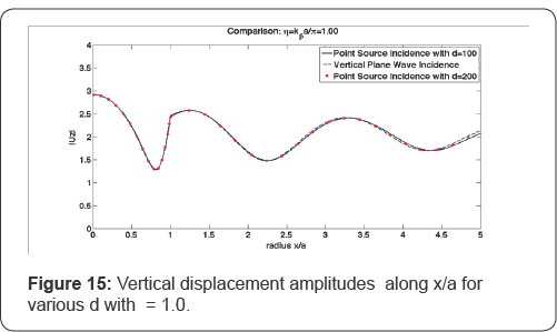
In Figure 15 to Figure 17,
the results of the normal plane incidence and of the normal
point-sourced incidences with various depths are visualized and
compared. Both the point source and the plane wave are normalized to
have unit amplitude displacement at the origin, or center of the canyon,
corresponding to free field displacement amplitude of 2 at the
half-space surface, after adding the reflected wave. The patterns of
amplitudes always agree at the lower range of x/a first closer to the
canyon, and then start to differ slightly when the referenced point
moves farther away from the canyon. For the case of = 1 in Figure 15, the plot of d = 100a can visually match the result of the plane incidence up to x/a = 2.5; but for η = 4 in Figure 16, the agreeable range shrinks to be around x/a = 2 along the horizontal axis; and for η = 8 in Figure 17,
this number of the upper-bound is only less than two. Thus, for a
point-sourced incidence at a fixed depth, the high incident frequency
narrows the efficient range of a substituted plane incidence.

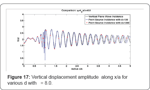
For this, when the frequency is not super high, the
plane incidences can be used for the simulation of the point-sourced
incidence assumed to be located deep such as d = 200a for η = 1, d = 500a for η = 4, and d = 1000a for η
= 8 which can guarantee the good matches along the radial distance up
to 5 in these figure presented. Note that in all cases, the differences
show up as phase shifts, while their amplitudes do agree.
Conclusion
This paper applies the series expansion of odd-order
Legendre polynomials to the wave diffraction around a hemispherical
canyon by a vertical point-sourced P-incidence. Results of various
source depths and dimensionless frequencies are discussed. Following are
the major aspects summarized for this problem:
1. The antisymmetric image method and the odd-order-
only Legendre polynomials can be effectively used to relax the
zero-stress boundary conditions on the half-space. The calculable range
of is high, although the highest selected in the discussion is 20.
2. The oscillations are intensive near the rim of
canyon, in particular for the case of high . So that the “dip and spike”
effect also exists in the point-sourced problems.
3. A higher must result in a more complex oscillatory
pattern on the surface of canyon, and the half-space. The same
conclusion was already made for the normal plane P-incidence in the
previous paper [1].
4. For incidence with a shallow epicenter, the
substantial impacts can be caught on the canyon surface, while the
influence on the surface of the half-space is relatively trivial and
decays rapidly to zero.
5. For incidence with a deep epicenter, its impact on
the half-space surface in the near range is comparable to that on the
canyon surface. The deeper source and higher frequency both help extend
the range of impact. However, the amplitudes will drop to zero at a far
distance eventually as long as the incidence is point-sourced.
6. The statement in [2]
“the results suggest that for the frequencies of interest in earthquake
engineering, the plane-wave representation of incident SH waves will
lead to reasonably realistic predictions of amplification of strong-
motion amplitudes on the ground surface” still holds for the 3-D
vertical P-wave incidence as well as for a larger range of the
dimensionless frequencies.
A. Mow and Pao (1973)
The stress and displacement functions:


Where z(i)n(.) , i = 1,3, are separately referred to the first kind of spherical-Bessel function with order n njn (.) and first kind of Hankel function with order nh1n(.) .
B. Derivation of Scattered Waves for Normal Point- Source P-wave Incidence
This part is to prove the validity of the
odd-term-only Legendre polynomials of the scattered P-and S-waves. The
scattered waves by a hemispherical canyon in the half-space can be seen
as the superposition of waves from two full space models of the
spherical cavity: Model 0 and Model 1.
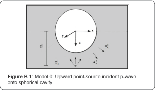
Model 0 is described in Figure B.1,
that there is a source located below the cavity, on the positive z-axis
with a distance d, emitting the P-wave radially. The P-wave is
propagating on the x-z plane and it interacts on the spherical cavity
surface then generates the scattered P- and SV-waves. (Term exp (-iωt) is omitted in all equations for convenience.)
The potential of the incident P-wave is given by

Where r is the radius and u - cosθ. that is the polar angle of the spherical coordinates that is sharing the same origin with the Cartesian coordinates in Figure B.1.
The scattered waves due to presence of the spherical cavity can be expressed in the following form:

Both expressions are independent of the spherical coordinate since the model is axisymmetric. Coefficients An and Cn can be solved exactly by the boundary conditions
σr = τrθ = 0 (B.3)
At r = a where is the surface of the spherical cavity. Thus φs0 and χs0 form a complete solution of this wave problem that was already solved in the 1970s [8].
Similarly, a 2nd full space model will be considered. Different from Model 0, Model 1 in Figure B.2 depicts a source right above the spherical cavity in the same way. A new Cartesian coordinate system is adopted here where,
x1 = -x, y1 = -y, z1 = -z. (B.4)
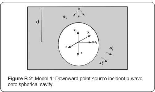
(r1,θ1,φ1) is the spherical coordinate system corresponding to the Cartesian coordinate system (x1,y1,z1) . With u1 = cosθ1 , the incident P-wave potential φi1 in Fig.B.2 can be expressed as

With φ1 as its amplitude. The resultant scattered wave potentials φs1 and χi1 in the coordinate system (r1,θ1,φ1) are given by

Which are in the same form of φs1 and χs1.
The coefficients of the scattered potential are again completely solved
because Model 1 can be taken as an adapted case of Model 0. From the
following relationships between coordinates (r,θ,ø) and (r1,θ1,φ1) from (B.4) that
r1 = r, θ1 = π - θ, θ1 = 2π - φ,
There is u1 = cosθ1 = - cosθ = -u. (B.7)
And φs1 and χs1 are then also given by, w.r.to. (r,θ,ø) :

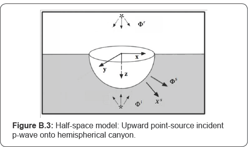
The half-space model is next considered. Figure B.3
shows a hemispherical canyon with center located at the origin of the
Cartesian coordinate (x, y, z) that of the same description as before,
and the entire x-y plane (z = 0) is the half-space surface, with z > 0
the elastic half-space. A point-source P-wave with potential φi vertically below the canyon will result in a point- source P-wave with potential φr vertically above the canyon, so that, from (B.1) and (B.5),

With both φi and φr , their superposition needs to satisfy the zero-stress half-space boundary conditions, then φ1 = - φ0 . Take φ0 = 1 so that φ1
=-1. Then, as discussed in Section 3 above, the two point sources
together with will satisfy the zero-stress half-space boundary
conditions of (6). The half-space model in Figure B.3 can now be considered as a superposition of the models in Figure B.1 and Figure B.2 such that
φi of Half-Space Model = φi0 of Model 0,
φr of Half-Space Model = φi1 of Model 1. (B.8)
In other words, the half-space model is the
superposition of Model 0 and Model 1. The presence of the hemispherical
canyon will result in the scattered wave's and ,χs which can be taken as the superposition of the scattered waves of Model 0 and Model 1:

From the above equations

Which is with the odd-degree-only terms and A'2n+1 = 2A2n+1. Similarly,

Which is also with the odd-degree-only terms and C'2n+1 = 2C2n+1
. Equations (B.11) and (B.12) are now the complete solution for the
scattered waves to be used in the paper, (16) above, which has been
shown to satisfy the zero-stress boundary conditions at the half-space
surface. They are the superposition of the complete solutions from Model
0 and Model 1.
For More Open Access Journals Please Click on: Juniper Publishers
Fore More Articles Please Visit: Civil Engineering Research Journal


Comments
Post a Comment