Fire Induced Airflow Study: Neutral Plane Height Estimation as a Function of the Heat Source Position- Juniper Publishers
Juniper Publishers-Journal of Civil Engineering
Abstract
Several numerical simulations of fire induced airflow
in a compartment were performed using the Fluent CFD code, in order to
establish a mathematical correlation linking the neutral plane height as
a critical ventilation parameter and the three-dimensional coordinates
defining the fire source location within the room. The fire is modeled
by a volumetric heat source (VHS approach) and the induced transport
flow phenomenon is considered as a buoyancy-induced turbulent flow.
Resolution of the governing equations comprises the Reynolds averaged
Navier-Stokes (RANS) equations using the k-e turbulence model combined
with an enhanced wall treatment.
Keywords: CFD; Neutral plane height; Fire induced flow; Correlation; Heat source location Introduction
Fire smoke propagation inside enclosures aroused for a
long time the interest of researchers who are still trying to elucidate
this complex phenomenon by various methods in order to determine the
smoke spread characteristics [1-4].
Researchers also count various parametric studies aiming to determine
the impact of geometric and thermal parameters acting on this flow type.
Steckler et al. [5]
was among the first researchers who conducted a series of full-scale
experiments studying the fire induced flow evolution inside a
compartment as a function of several parameters like the fire strength
and location and the shape and size of the openings.
Results provided by Steckler et al. [5]
are regarded as the most comprehensive full-scale experimental data and
are also essential for every validation task of a fire modeling codes.
These experimental results were subsequently used as a database for
further numerical studies as those conducted by G.M. Stavrakakis et al. [6], who based on the Steckler et al. [5]
results, have developed a CFD numerical model able to properly
reproduce the experimental results and to correctly predict the thermal
and dynamic flow field pattern and to extend the induced fire flow study
to a more complex configuration (two- room enclosure).
As fire induced flows in compartments are essentially
qualified as buoyancy driven flows, these types of flows are strongly
affected by the location of the heat source inside the compartment
considered. Thus, investigating the fire location impact for different
fire scenarios was the principle object of a large number of recent
researches [7-12].
In spite of this significant number of research works on the heat
source location effect, there is no direct calculating method which
provides the ventilation parameters ; the flow rate at the opening and
the neutral plane height as a function of the heat source position
inside the enclosure.
Further to this finding and in order to complete our
previous study about numerical simulation of a fire induced airflow in a
compartment [13],
which has only treated the mass flow rate at the opening as a crucial
ventilation parameter, we propose in the present work a second general
mathematical correlation between the position of the fire source inside
the fire room, and the neutral plane height at the doorway exit as the
second crucial ventilation parameter in a fire induced flow study.
Numerical Modeling
Physical problem
In the present study, we focus on the problem of fire
induced airflow in a compartment naturally ventilated via an opening
door. The expected steady flow field for the case with a central fire
source is illustrated in Figure 1a.
The smoke distribution is represented by the red color while the
external fresh air is colored by the white one. Due to buoyancy force
generated around the heat source, the fresh air enters into the room by
the low part of the doorway with a flow rate noted (ma) shears or entrains some gas from the hot upper layer at a rate of (mg).
This process leads to the formation of the so- called cold lower layer
and the hot upper layer. Opening mass flow rates are determined by
integrating the local mass velocities ( ) over the area of the door
opening (H) either above or below the zero velocity plane, the so called
neutral plane height (N) characterizing the height of the boundary
between hot and cold layers.

Geometry and mesh
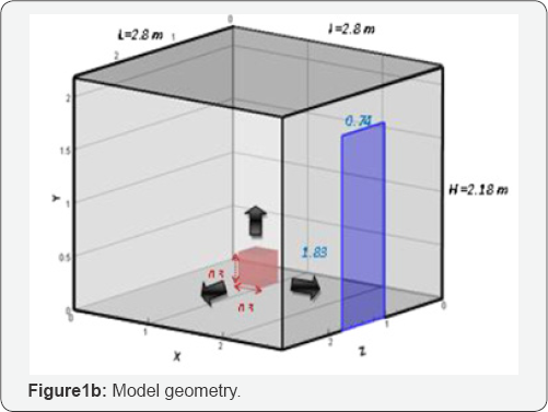
Basing on the fire room configuration adopted by Steckler et al. [5], the geometry developed in this work consists of a room (2.8 x 2.8x2.18 m3) with a centrally located cubic burner (0.3x0.3x0.3 m3) as it can be shown in Figure 1b.
The burner is modeled by a volumetric heat source (VHS approach)
emitting a total heat releasing rate of 62.9kW. The fire room is
naturally ventilated via an opening door of dimensions (1.83x0.74 m2) as it can be shown in Figure 1b.
During the simulations several positions of this burner inside the
compartment were investigated corresponding in each case to the
variation of the height position (y -axis variation), the transverse
position (z axis variation), and the longitudinal position (x- axis
variation) presenting various locations where the fire may be triggered.
The three dimensional coordinates of each source position tested during
the simulations are given in Table 1.
The mesh grid generated for this geometric configuration is formed by
658,000 cells strongly tight in the tiles, close to the heat source, at
the
doorway and in the vicinity of the walls (Δ Χ= ΔΥ=10-3)


Further, the mesh grid is a little l (Δ Χ= ΔΥ=10-2)
Governing equations
Numerical simulation of the problem considered
requires the resolution of the general conservation laws of mass
momentum and energy namely the Navier-Stockes equations, performed
taking into account the following assumptions:
a) Steady State
b) Turbulent regime
c) Incompressible fluid (air)
d) Boussinesq approximations
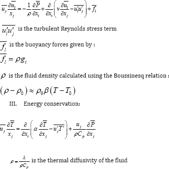
Given the Reynolds decomposition, the conservation equations are written as follows:
I. Mass conservation:

II. Momentum conservation:

Boundary conditions
Referring to the experimental data of Steckler et al. [5], the appropriate boundary conditions fixed at the domain limits are as follows:
a. The walls of the compartment are considered adiabatic
b. The burner is modeled as a volumetric heat source emitting a total power releasing of 62.9kW
c. The velocity, the temperature and the pressure outside
the computational domain are taken as equal to the ambient
conditions (T=300 K, P=1.01325*1005 Pa).
Computational details
The numerical resolution of the problem is performed
based on a finite volume method with the segregated solver to solve the
time averaged Navier Stokes equations. The standard k-£ turbulence model
coupled with the Enhanced Wall Treatment approach is used to treat
turbulence effects, which validity and reliability in simulating fire
induced airflows in compartments were proven satisfactory in our earlier
work [14]
since the discrepancy noted in the flow characteristics predictions
does not exceed 3%, as compared the experimental results of Steckler et
al. [5].
This modification (Enhanced Wall Treatment) enables to eliminate
problems occurring at the walls vicinity and ensures better accuracy of
the numerical results.
To ensure accuracy of the results, the convergence
criteria for the continuity, velocity and turbulence terms has been
fixed in residual values to be less than 1e-04 while a value of 1e-06 is imposed for the energy.
Neutral Plane Calculation
In a case of fire, the ventilation parameters; the
mass flow rate at the opening and the neutral plane height are crucial
to find out. Knowing that these parameters mainly depend on the heat
release rate emitted by the fire source and its location within the
configuration considered as mentioned in several research works
[5,8-11,15], it would be interesting to look for a mathematical
correlation linking these two parameters to both of these variables.
Given that in our earlier work [13],
we established a first mathematical correlation allowing to calculate
the mass flow rate at the doorway according to the three-dimensional
coordinates of the heat source within the fire room, we propose in this
present work a second mathematical correlation enabling to calculate the
neutral plane height according to the heat source location within the
compartment fire studied as an important parameter in a fire induced
flow study, since it since characterizes the height of the boundary
separating the fresh air entrance and the toxic fumes exhausting through
the door. An elevated height of the neutral plane ensures a greater
extent for the fresh air entrance into the compartment
In order to establish a general mathematical
correlation between the neutral plane height and the heat source
position within the fire room, a dimensionless analysis must drawn up:
The height of the fire room, H, is taken as the characteristic length,
so the dimensionless coordinates variables defining the heat source
position are set as:

The dimensionless neutral plane height consequently becomes:

Results deduced from the various numerical simulations corresponding to the different heat source positions tested (Table 1)
have provided a wide range of the neutral plane height. The different
values of the neutral plane obtained, are varying according to the
three-dimensional coordinates defining the heat source position within
the fire room.
N*s = B x( xs* )a x(y*s )b x(Z*S )c
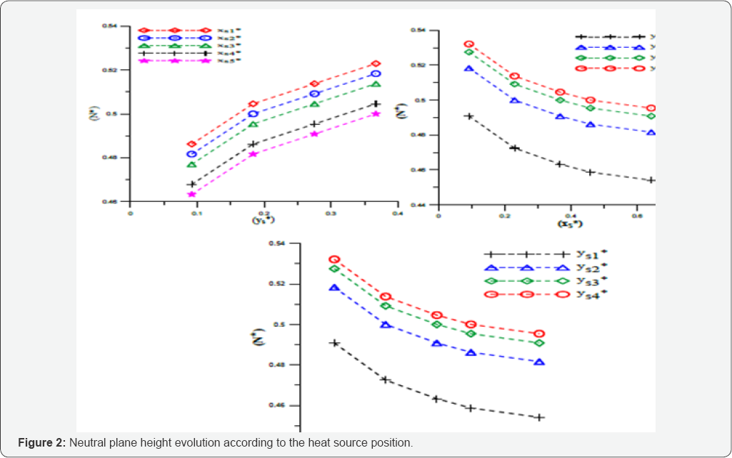
We represent in Figure 2, the evolution of the dimensionless neutral plane obtained according to the different positions of the heat source tested.
It can be clearly seen from Figure 2 that the neutral plane height decreases when the heat source is positioned at a higher
transversal ( X*s) or longitudinal position ( Z*s), however it increases with the increasing of the height position of the heat
*
source (y*s ). But in all cases, the
dimensionless variable follows a power law as a function of three
dimensionless variables. This evolution has prompted us to use a
logarithmic scale enabling to better follow the dimensionless neutral
plane height progress
(N* * ) according to different dimensionless variables
defining the heat source position inside the room. This logarithmic
evolution is given in Figure 3.


Profiles shown inFigure 3
, show that the dimensionless neutral plane height evolution is
following a linear profile according to the three-dimensional
coordinates defining the dimensionless heat source position, giving rise
in each case to parallel lines having a same slope of -0.03 for the
longitudinal and
transversal coordinates ( X*s ) and ( Z*s ) and 0.05 for the height
*
position ( y*s ). Such linear logarithmic scale
developments led us to seek a mathematical correlation between the
neutral plane height and the dimensionless position of the heat source
as follows:
The coefficients a, b and c are deducted from the slopes of the different parallel lines obtained in Figure 3, and are respectively -0.03, 0.05 and -0.03.
We can finally represent the different neutral plane height obtained from the totality of the heat source positions tested (Table 1). This final evolution is given on Figure 4.

As it can be seen from Figure 4,
the dimensionless neutral plane height corresponding to the heat source
positions tested during simulations can be combined into a single
linear line with a slope equal to 0.525.
This linear line represents correctly and well the
evolution of the dimensionless neutral plane height (N*) as a function
of the heat source location since the coefficient of determination R2 is
equal to 0.99. Finally, the neutral plane height can be expressed as a
function of dimensionless heat source position by the following
mathematical relationship:
N*s = 0.525 x( x*s )-0.03 x( y*s )x( Zs )-0.03
The established mathematical correlation can
perfectly provide the value the neutral plane height in case of fire,
regardless of the position of the heat source inside the compartment,
which represents a very useful outcome especially for compartment fire
scenarios when the heat source triggering the fire is located at a
distance from the floor such as the case of a lamp, a computer or a
heater rarely placed at the floor level, but usually on a table or at
some height in the room. This finding would avoid engineers to optimize
and to enhance fire safety measures in case of fire by determining with a
simple and direct way the optimal location of smoke detectors or
exhaust vents inside buildings by directly calculating the ventilation
characteristics and the vents position for smoke extraction for each
specific study especially without having to carry out any experimental
measurements nor numerical simulations.
Conclusion
Based on the fact that the fire induced airflow in
compartments mainly depends on the heat source position inside the
considered configuration, and as a continuation of our earlier work [13],
several CFD simulations were performed in order to find out a
mathematical correlation that links the ventilation characteristics,
primarily the neutral plane height at the doorway, to the heat source
location within the compartment. Thus, The establishment ofthe
mathematical correlation allowing to calculate the mass flow rate at the
doorway according to the three-dimensional coordinates of the heat
source within the fire room constitues the main finding of this research
work. A CFD result obtained in this study has allowed establishing a
general correlation able to calculate the neutral plane height through
the doorway regardless the fire position within the fire room.
Consequently, this result avoids future researches to conduct
experiences or numerical simulations aiming to calculate this
ventilation parameter especially when the heat source is placed at
several locations in the fire room, which could be really useful to
enhance fire safety measures and to provide the best location of smoke
detectors or exhaust vents inside buildings by predict their optimal
location for each specific case study especially when the trigger source
is located at a height from the ground (lamp, computer, curtain...).
For more open access journals please visit: Juniper publishers
For more articles please click on: Civil Engineering Research Journal


Comments
Post a Comment